Note: The printer must not be powered on when flashing the firmware using ST-Link.
¶ Preparation
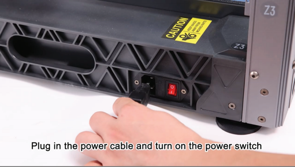
1.Plug in the power cord and turn on the power switch
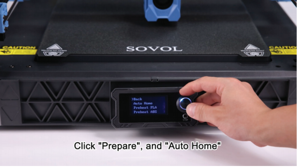
2. Select “Prepare” - “Auto home”.
¶ Assembly part
¶ Clean the module
(make sure the power is turned off and unplugged before disassembly)
1. Take out the nozzle to clean the module, silicone brush, steel sheet, Phillips screwdriver.
2 Use a H2.5mm screwdriver to loosen the M3 fastening screw of the pressure switch.
3.Unplug the communication cable from the pressure switch and set it aside.
4.Store the disassembled pressure module in a safe place.
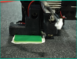
5. Fix the silicone brush and nozzle cleaning sheet metal on the nozzle cleaning module.
6. Secure the filament breakage detection communication cable using Kapton tape.(This step must be done)
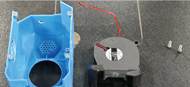
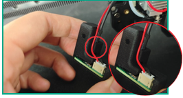
¶ Eddy current module
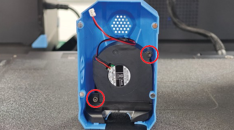
1.Remove the nozzle fan cover.Carefully disconnect the fan cable from the fan cover.
 |
 |
2. Disassemble the housing and remove the old cooling fan.(Retain the original fan cover for potential future use.)
3. Remove the fan and air guide from the old fan cover.
¶ Install a new fan cover
1.Install the fan into the new fan shroud, paying attention to the position of the wiring harness.
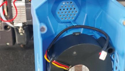
2. Install the fan guide nozzle, snap the guide nozzle into place.
3. Tighten the screws of the fan with an H2.0 screwdriver(. Max. torque 0.196 N.m)
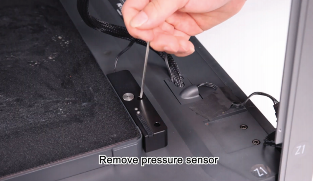
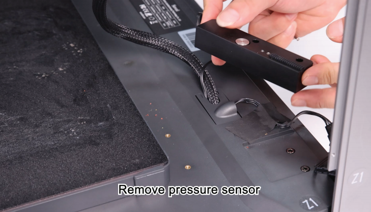
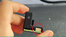
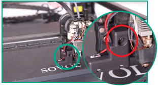
¶ Remove the proximity switch
1. Loosen the pressure sensor M3 screw on the printhead communication board.
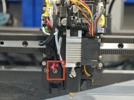
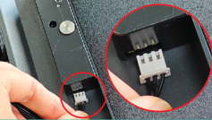
2. Unplug the communication line of the proximity switch
3.Please refer to this diagram for the pressure sensor port.
Note: If adhesive is present on the wiring terminals, remove it before disconnection.
¶ Install the proximity switch
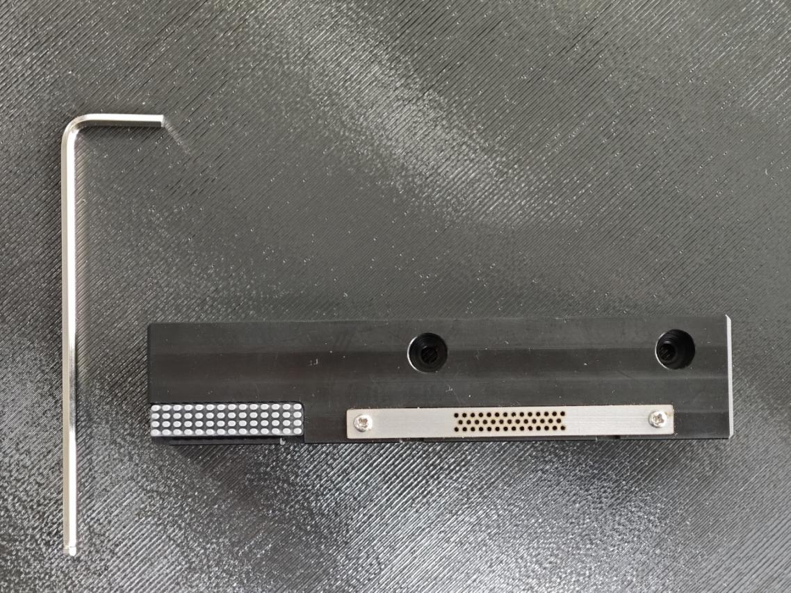
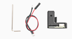
1.Locate the eddy module, H2.5mm wrench and the communication cable for the eddy module from the package.
2.Observe and find the 4Pin terminal on one end of the communication wire of the eddy current module.(The colors of the cables may vary.)
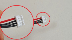
3.Connect the 4Pin terminal on one end of the communication cable of the eddy module to the corresponding pok on the PCB circuit board of the eddy module.
4. For fixing the communication cable of the eddy module, break the communication cable through the reserved slot on the eddy module mounting.
5.Clean any remaining filament from the nozzle.
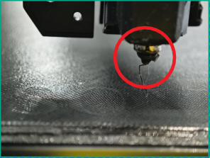
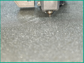
6..Make sure the nozzle is in direct contact With the hot bed(If you are using a new version of the eddy module, you can skip 6-8)
7.Prepare a spacer approximately 2 mm thick (e.g., a 3D-printed part or layered material).
8. Place this item under the eddy module.
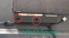
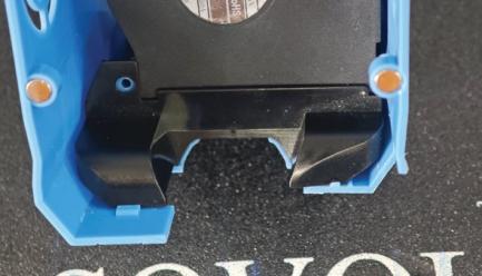
9. Attach the eddy module to the nozzle and fasten with M3x12 screws.(Max. torque 0.196 N.m)
10. The communication wire from the eddy module is routed through the harness on the left side of the radiator aluminum block. (Do not allow the cable to come into contact with the heat sink.)
The assembly is complete.
¶ Configuration section
¶ Preparation(Windows only)
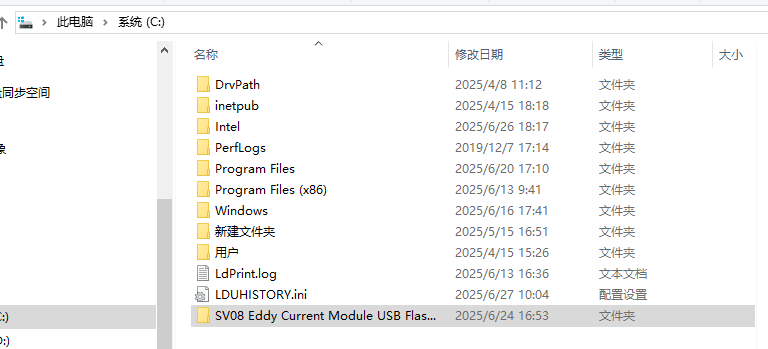
1. Insert the USB flash drive we provided into your Windows system and open the ST-LINK Driver folder.
2. Copy the files in the USB flash drive to the computer
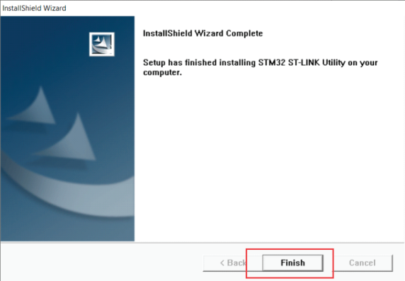
¶ Install the ST-LINK utility.
(If you already have the ST-LINK utility installed, ignore this step)
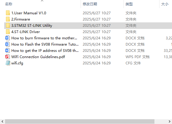
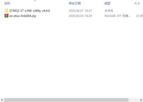
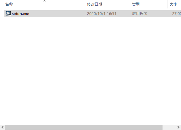
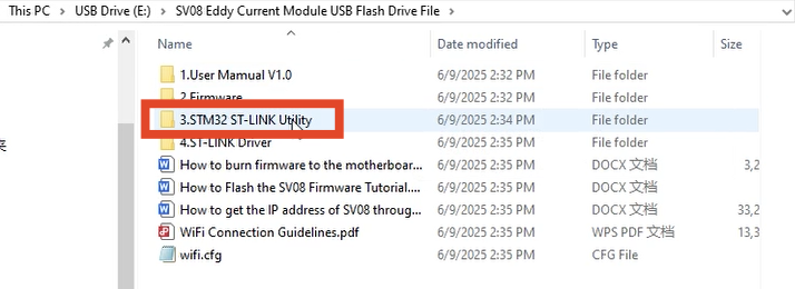
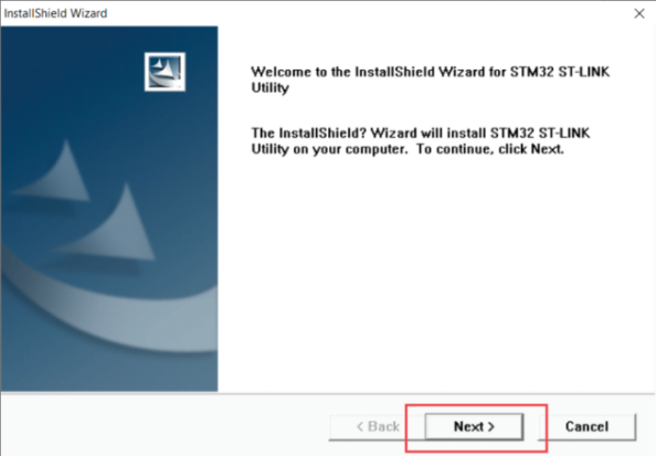
1. Run "3.STM32 ST-LINK Utility" - > "setup.exe" in the compressed file "STM32 ST-LINK Utility v4.6.0"
 |
 |
 |
2. Open the "stlink driver installation package" folder in the document.
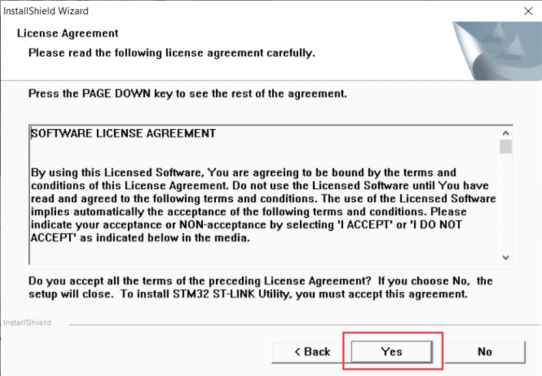
3. Click “Next”.
4. Click “Yes”.
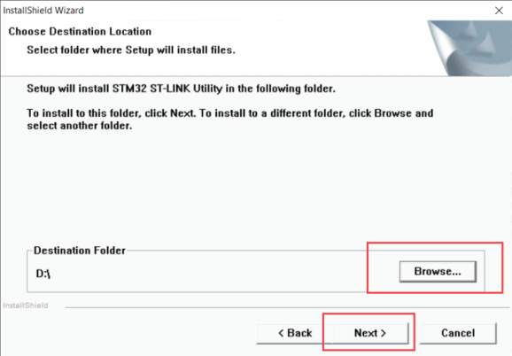
5. Select the installation location and click "Next".
6. Click “Finish”.
¶ Flash the motherboard firmware
¶ Preparation
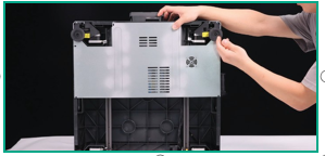
1. Rotate the printer to position its bottom panel facing forward.
Warning: Ensure the printer is placed on a stable surface and properly secured before proceeding.
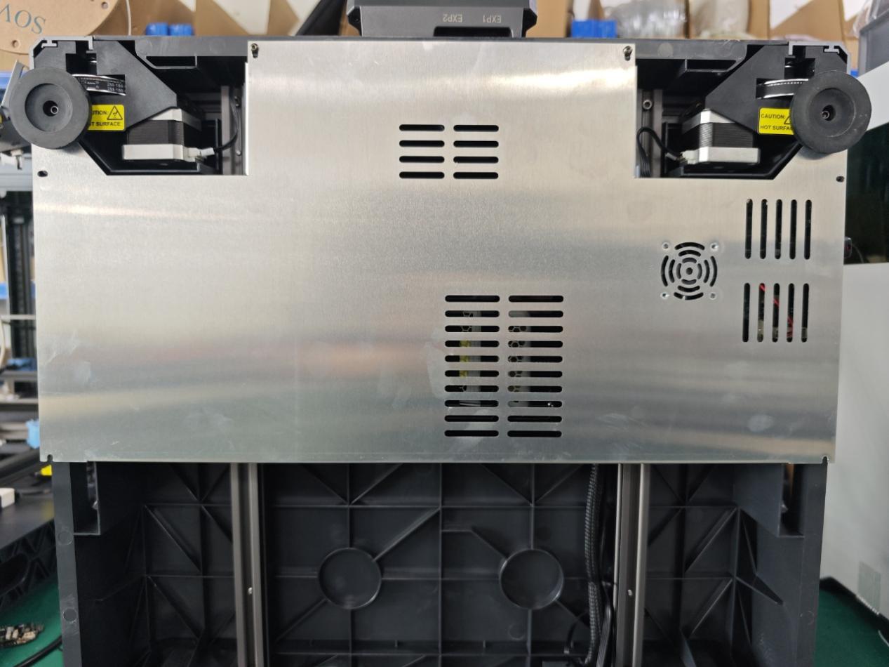
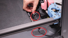
2.Remove the protective sheet metal, note that there is a fan cable here, and this fan cable is connected to the PCB board that needs to be flashed firmware.
3.Keep the sheet metal and screws in a safe place
¶ Start flashing the firmware
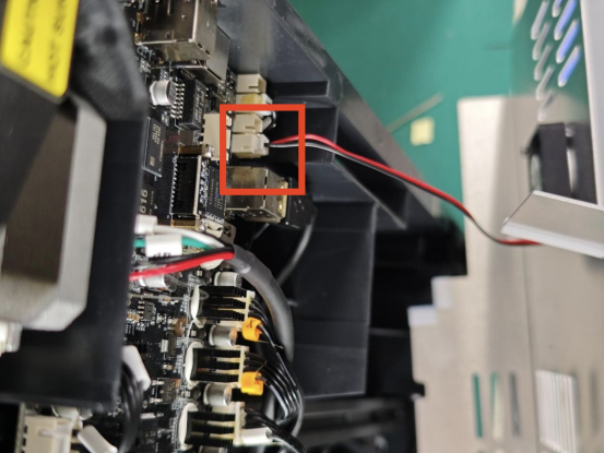
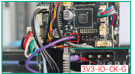
1. Connect the ST-LINK programmer and the mainboard.
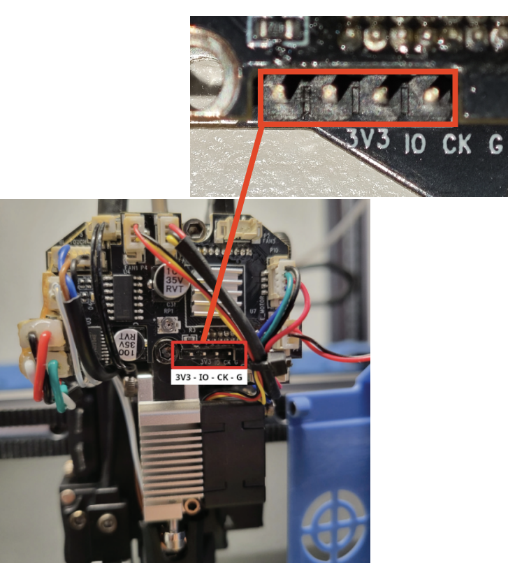
2. Connect according to the line sequence:
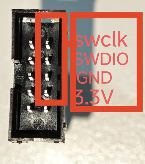
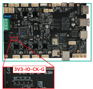
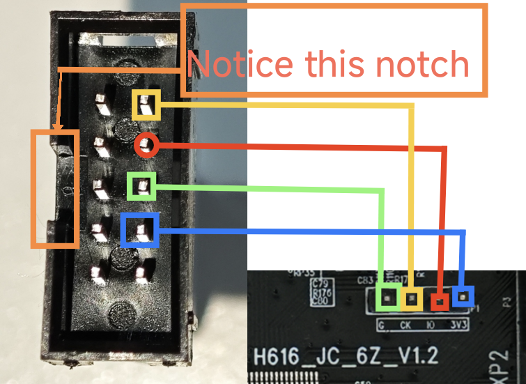
3.3V to 3V3, GND to G, SWDIO to IO, SWCLK to CK.
 |
 |
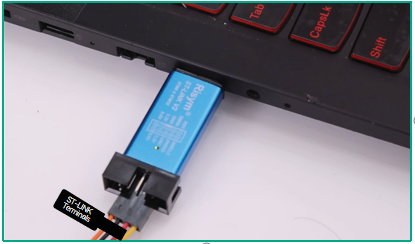
3.Plug into the computer USB por(St-link only suppoks Windows systems)
4.Flash the mainboard firmware from the USB drive.
Note: For SV08 models, the latest firmware is compatible with both the mainboard and the adapter board.
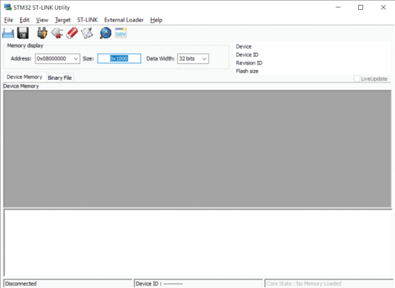
5.Open ST-LINK Utility.
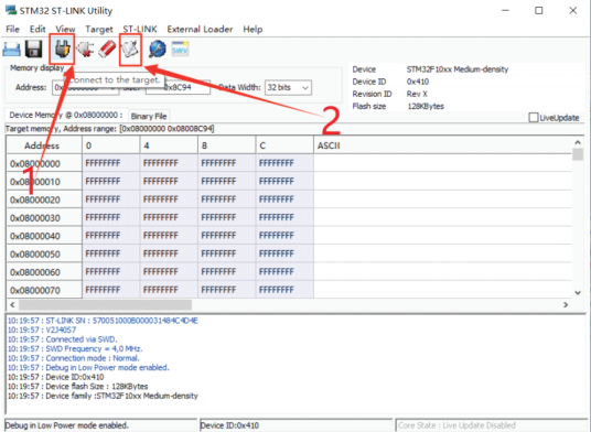
6 Click the connection icon, then click the open file icon
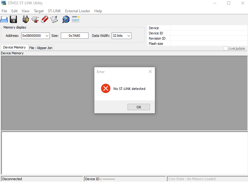
7.(1) If you click 1 and then alarm "No ST -LINK detected", detect whether the wiring is correct, if the wiring is correct, please re-plug the connection between ST -LINK and the U disk.
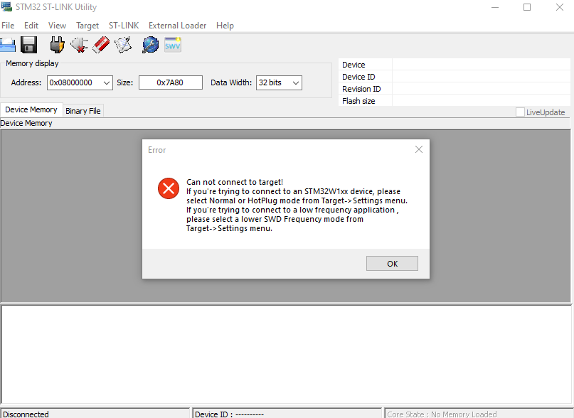
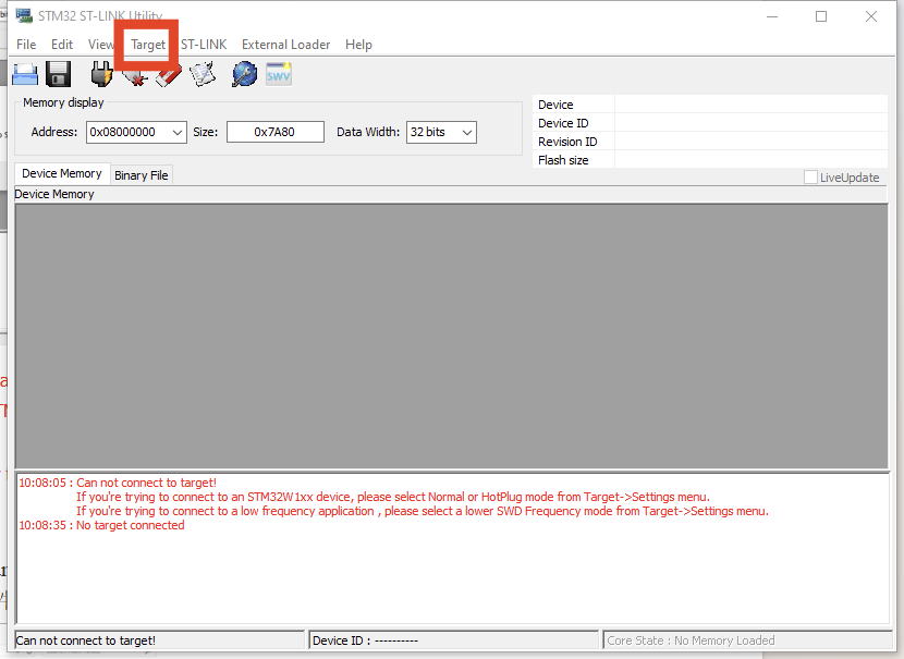
(2) After clicking 1, the software alarms "Can not connect to target!"
If you're trying to connect to an STM32W1xx device, please select Normal or HotPlug mode from Target->Settings menu.
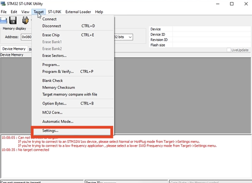
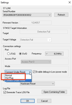
If you're trying to connect to a low frequency application , please select a lower SWD Frequency mode from Target->Settings menu.” Click on "Targer", then click on "Sttings...", find "Mode", click on the bottom triangle, and select either "Nomal" or "Hot Plug".
 |
 |
 |
 |
(3) After clicking 1, the software alarms "Can not connect to target!"
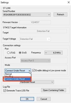
Please select "Connect Under Reset" mode from Target->Settings menu and try again.
If you're trying to connect to a low frequency application , please select a lower SWD Frequency mode from Target->Settings menu.” Select "Connect Under Reset" in "Mode"
(4)Note: If you keep alarming "7.3" and "7.4", please confirm whether the cable is connected, and replace the USB port to try 3 more times, if it really doesn't work, please contact SOVOL
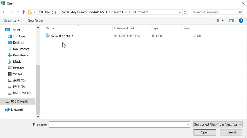
8.Open the “SVO8 Eddy Current Module USB Flash Drive File >2.Firmware” directory under the USB flash drive, find the bin firmware file, and click "Open".
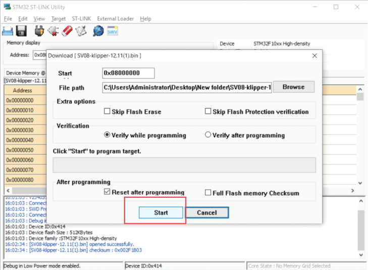
9 Click "Start".
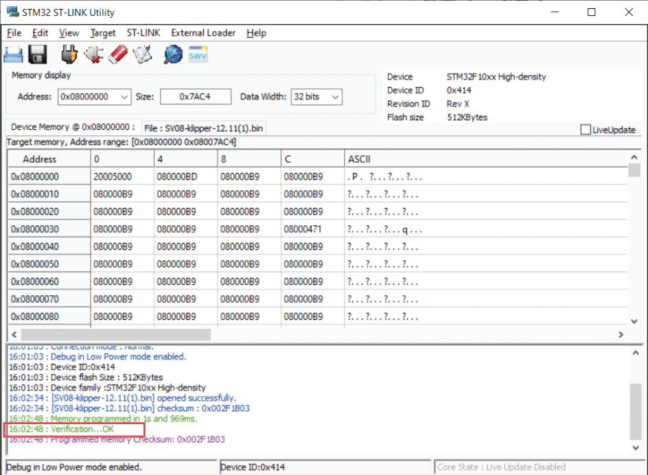
10 The display is as follows, indicating that the burning is completed.
¶ Flash the toolhead board firmware
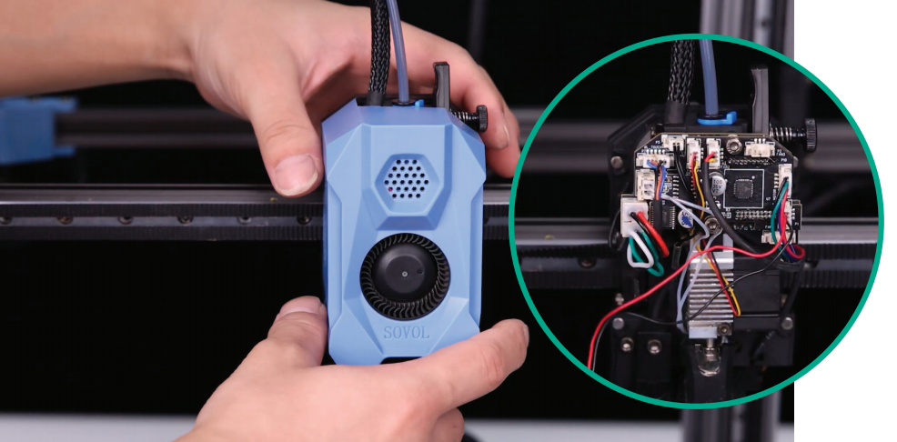
1.Connect one end of the ST-LINK to the PC and the other end to the position shown in the illustration on the printhead communication board. (the procedure is the same as refreshing the firmware on the motherboard)
2.Connect ST-LINK to PC. (St-link only suppoks Windows systems)
3. Open ST-LINK Utility.
4. Click the connection icon, then click the open file icon
5(1)If you click 1 and then alarm "No ST -LINK detected", detect whether the wiring is correct, if the wiring is correct, please re-plug the connection between ST -LINK and the U disk.
(2) After clicking 1, the software alarms "Can not connect to target!"
If you're trying to connect to an STM32W1xx device, please select Normal or HotPlug mode from Target->Settings menu.
If you're trying to connect to a low frequency application , please select a lower SWD Frequency mode from Target->Settings menu.” Click on "Targer", then click on "Sttings...", find "Mode", click on the bottom triangle, and select either "Nomal" or "Hot Plug".
|
|
|
|
|
|
(3)After clicking 1, the software alarms "Can not connect to target!"Please select "Connect Under Reset" mode from Target->Settings menu and try again.
If you're trying to connect to a low frequency application , please select a lower SWD Frequency mode from Target->Settings menu.” Select "Connect Under Reset" in "Mode"
(4) Note: If you keep alarming "7.3" and "7.4", please confirm whether the cable is connected, and replace the USB port to try 3 more times, if it really doesn't work, please contact SOVOL
6.Open the “SVO8 Eddy Current Module USB Flash Drive File >2.Firmware” directory under the USB flash drive, find the bin firmware file, and click "Open".
7 Click "Start".
8 The display is as follows, indicating that the burning is completed.
¶ Get back to work
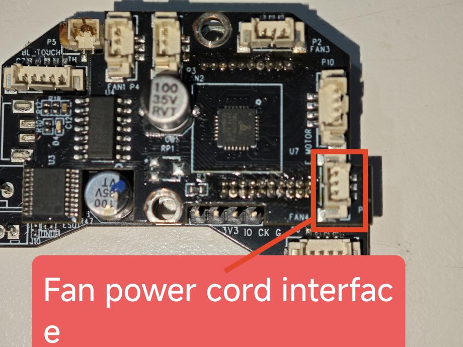
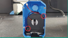
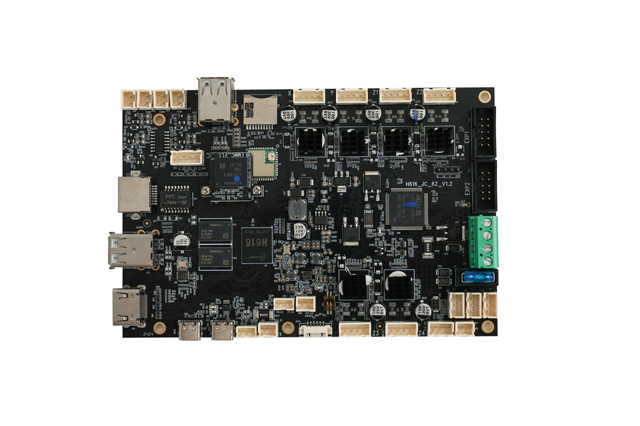
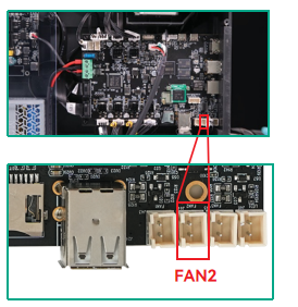
1. Connect the fan cable terminals on the metal plate cover to the“FAN2” pok on the motherboard.
2.Secure the metal cover plate using an H2.5 screwdriver.
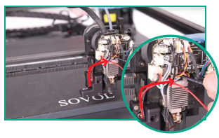
¶ Connect the eddy current cable
1.Turn the printer upside down to right it.

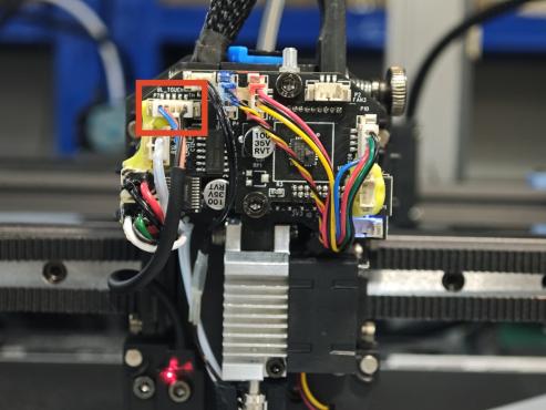
2.Connect one end of the eddy module communication cable to the “BL_TOUCH” pok on the printhead communication board at.
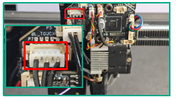
3. 1Pin pok on one end of the eddy module communication cable is connected to the “3V3” pok fixed on the nozzle communication board.
4.Connect the fan wire on the fan cover to the “FAN 4” pok on the spray head communication circuit board.
5. Align the opening at the top of the fan cover with the protruding position of the communication electronic board of the sprinkler, and then install it.
Note: Do not press against the wire when installing the nozzle cover.
¶ Dev upgrades
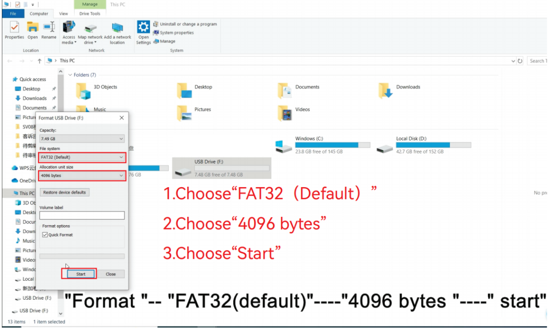
1. Open the folder that has been copied on the PC side, format the USB flash drive and use "FAT32" - '4096bytes' - "Start". 4096 bytes - Start. (If you don't have 4096bytes, choose 8192bytess)
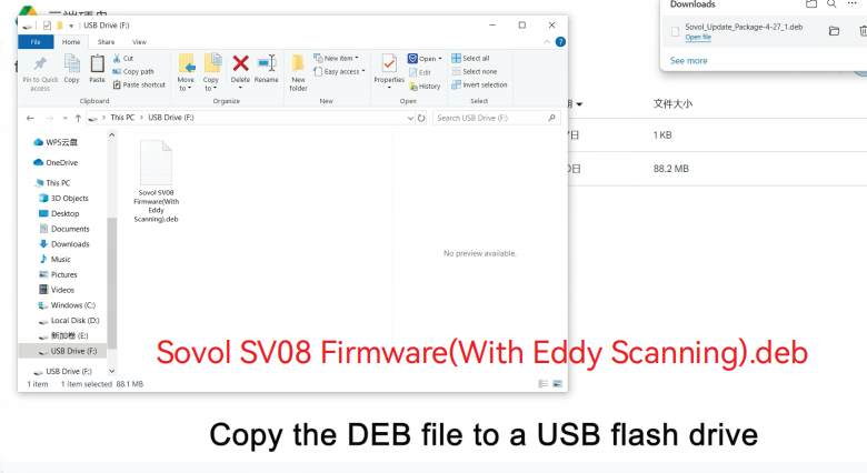
2. Copy the "2.Firmware"-"Sovol_Update_Package-06-05_2-4-9-eddy" file from the folder to a USB flash drive and make sure it is in the root directory. (Make sure there's only one file.)
3. Plug in the power cord, turn on the power switch, and wait about 30 seconds
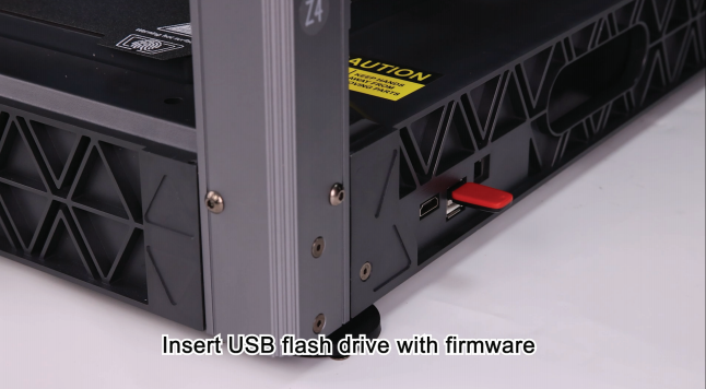
4.Insert the USB flash drive into the USB port on the printer.
5.Wait for 2-3 minutes, and the printer will enter the main interface smoothly after the upgrade is successful
(If you still can't enter the system after waiting for more than 5 minutes, please put the "Sovol_Update_Package-06-05_2-4-9-eddy" file in the USB flash drive to upgrade, or if it doesn't work, please contact "SOVOL")
¶ Debugging
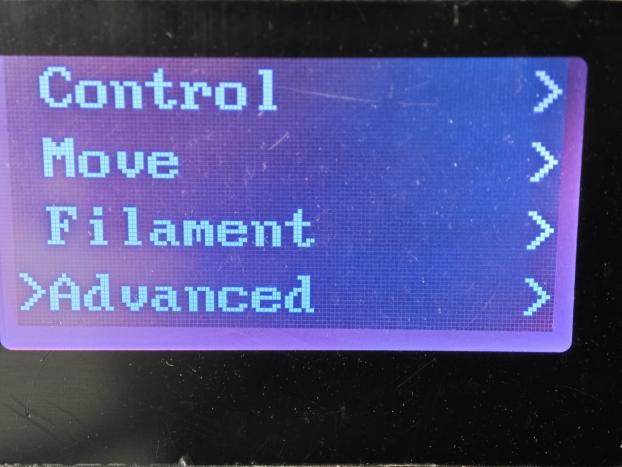
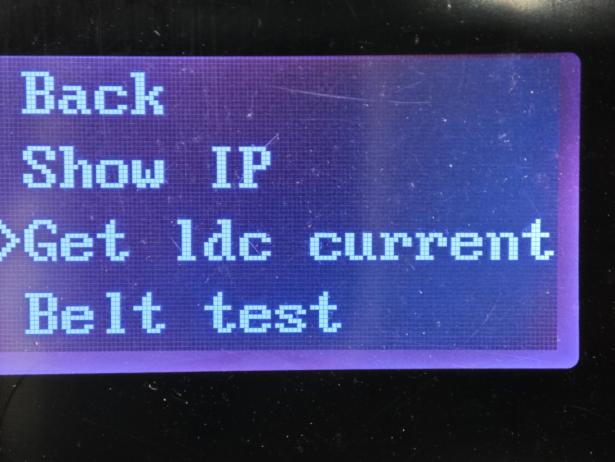
(1) Use the knob to select "Get ldc current" in "Advanced"
 |
 |
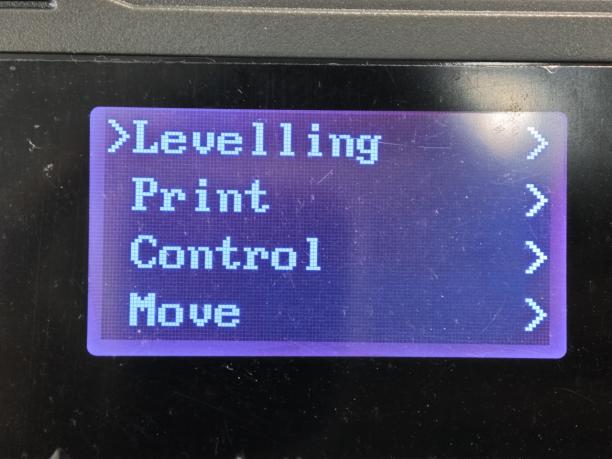
(2)Use the knob to select "Calibrate Eddy" in "Levelling"
 |
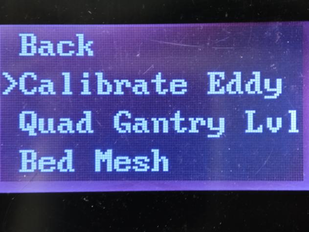 |
Note: Be sure to follow the order!
Once the operation is complete, you can start printing.
If there is an alarm during eddy current calibration, you need to go to mainsail to check the alarm message.
¶ Preparation (skip if connected)
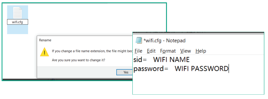
(1)Insert the USB flash drive, find the "wifi.cfg" file, open it with a text editor, and replace it with
Current WiFi name and password (Note: WiFi name cannot contain special characters,
Otherwise, it will not connect properly):
•ssid= WiFi name
•password= WiFi password
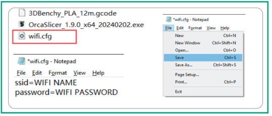
(2)Save the "wifi.cfg" file, making sure it remains in the root directory of your USB drive
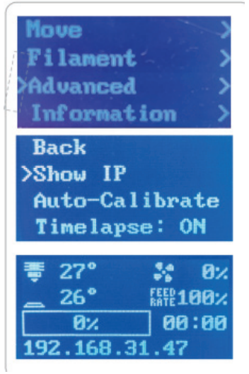
(3)Plug the USB flash drive into the printer and wait for 1 minute, then press the knob
Select "Show IP" and wait 5-10 seconds. The IP address of your home network will
Appear. If 127.0.0.1 appears, we need to check whether the Wi-Fi account and password are there
Whether the USB flash drive files are correct, or whether the USB flash drive is inserted correctly, and
Then restart your computer to do the above again.
(4)If you still can't connect, go to the following website (Note: If it still doesn't work, please contact SOVOL)
https://wiki.sovol3d.com/en/SV08-Troubleshooting/Unable-to-connect-to-WIFI
(5)If you don't have a "wifi.cfg" file in your USB drive, you can create one:
•Right-click the desktop and select New > Text Document to create a new TXT file.
• Rename this file to "wifi.cfg" with a lowercase extension.
•When prompted to confirm the file extension change, click Yes, effectively creating a new .cfg file.
(6)After the printer successfully connects to the network:
Select “Show IP” on the touchscreen to retrieve the printer’s network IP address.
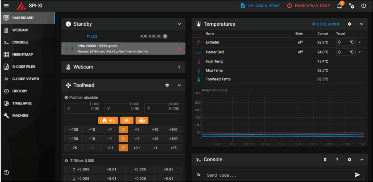
Enter this IP address into a web browser on a computer or mobile device within the same LAN to access the Mainsail interface.
¶ Formal commissioning
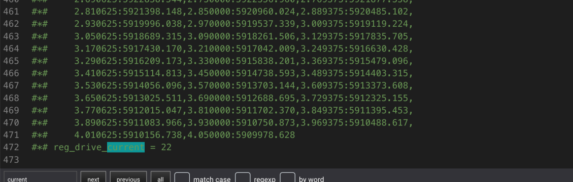
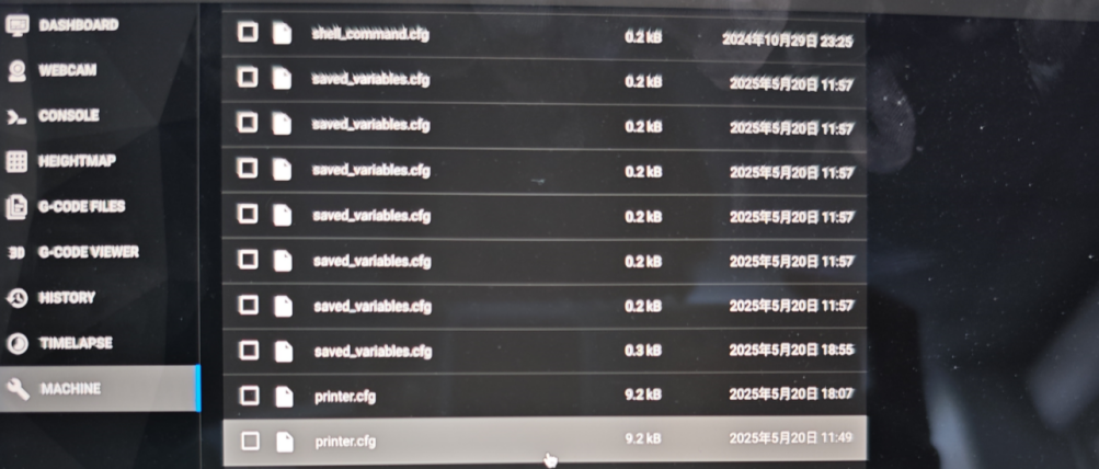
1.If the alarm message is "123", you need to enter the printer.cfg file
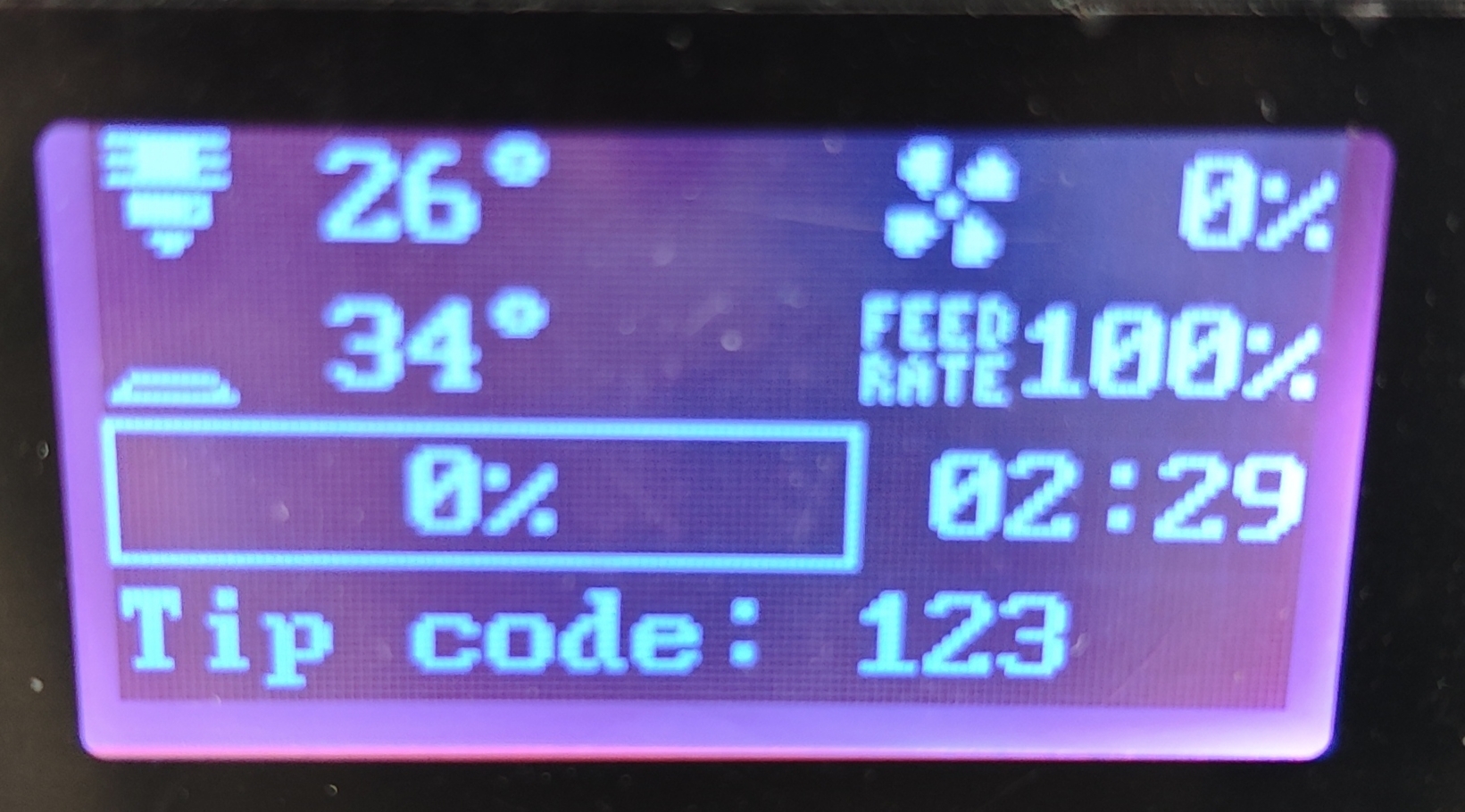
2.Scroll to the bottom to observe whether the number after = in "#*# reg_drive_current=" is 22, if not, change it to "#*# reg_drive_current=22" (Note: If 22 is still not available, please contact SOVOL)
3.Re-calibrate the eddy current, and after the calibration is passed, you can start using the printer.