¶ SV08 AB axis belt replacement and adjustment tutorial
When the following situations occur: The model appears to be layered and misaligned , the X-axis and the rear crossbeam are not parallel or the AB-axis makes a strange noise. It is recommended to check and debug the tightness of the synchronization belt.
 |
 |

|

|
Preparation steps:
Turn on the machine, click"Auto home", and then raise the AB axis of the printer to 200 height, easy to adjust the synchronization belt.
 |
 |
 |
 |
¶ Remove the gantry belt and calibrate the X-axis parallelism
¶ A. Remove the belt
1. Turn off the printer, completely loosen the fixing screw of the A/B idler tensioner, and turn the tightening screw counterclockwise to completely relax the X/Y belt on both sides and facilitate the removal of the X/Y synchronous belt.
 |
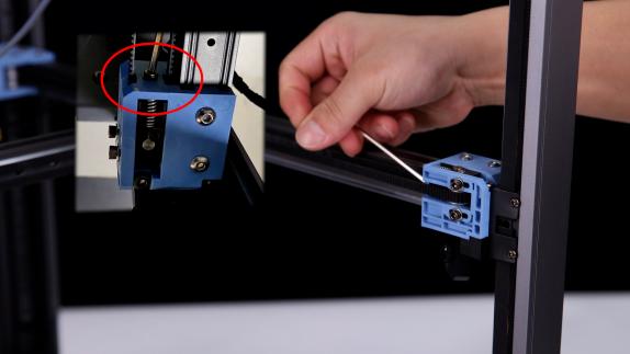 |
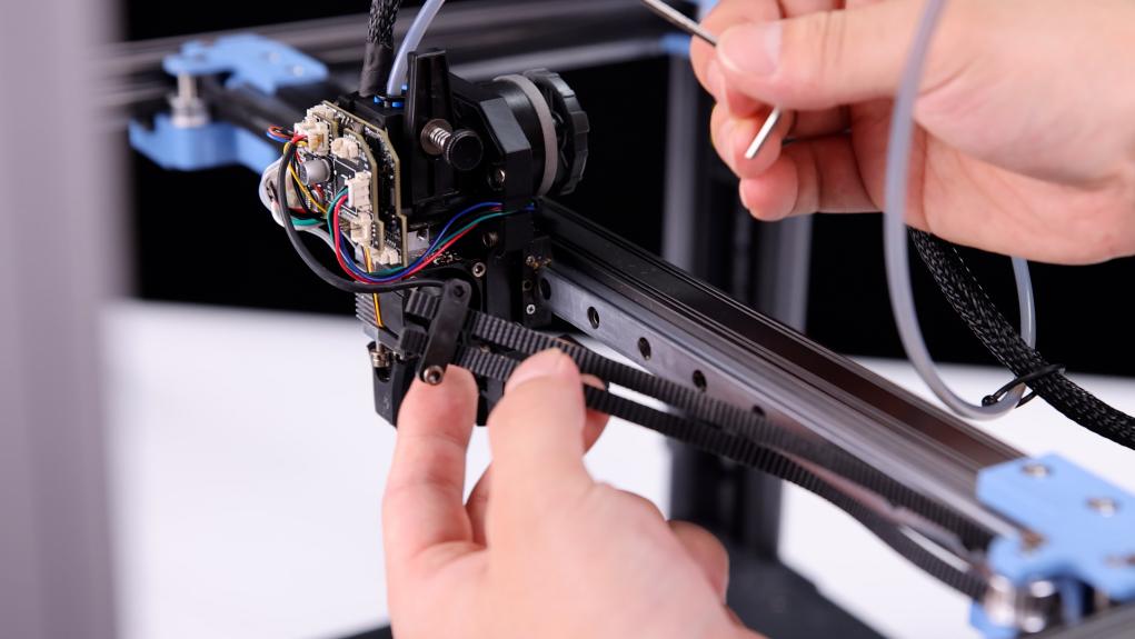
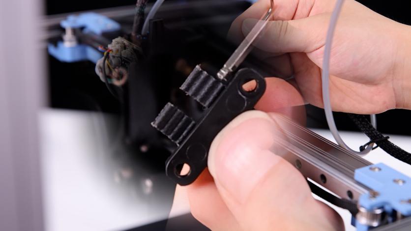
2. Take the belt and the fan cover of the nozzle down, unplug the cooling fan wire, loosen the fixing screws of the belt clips on both sides, and remove the two belts (please pay attention to the length of the belt when the belt is removed, subsequent installation of the belt is required to keep the belt length consistent, and the fixed position of the belt clip is about 3~4 teeth.)
(Belt Model: 2GT W:5.7mm L:1880mm*2)
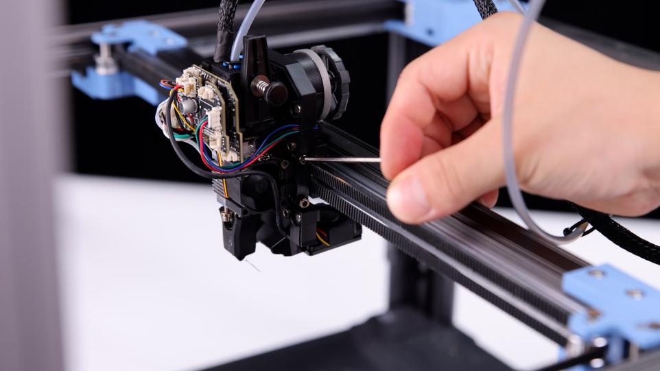 |
 |
 |
¶ B、Calibrate the gantry frame X-axis parallelism
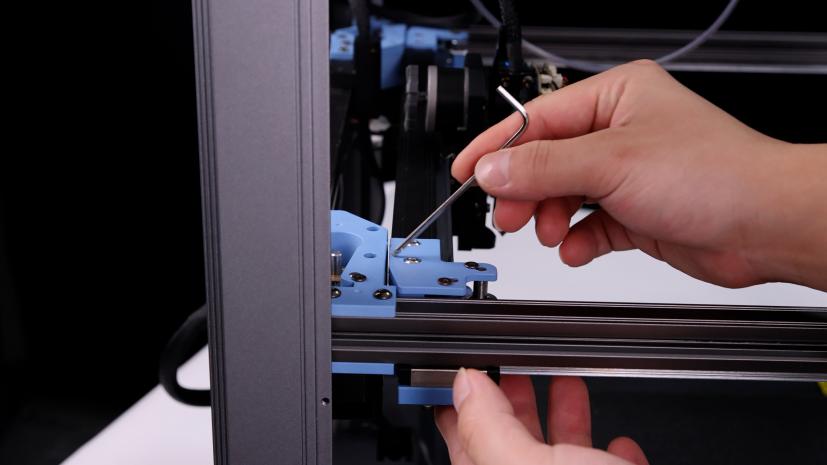
3. After removing the belt, please push both ends of the X axis at the same time (to avoid the situation of slight deformation of the X axis position caused by unilateral pushing and pulling), push the X axis to the back end of the gantry frame, the X axis should be close to the AB axis motor base backward, and there should be no gap between the X/Y joint and the A/B axis motor base.
 |
 |
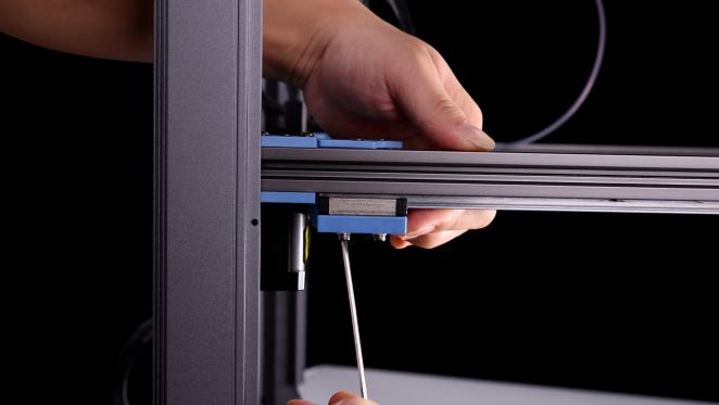 |
(If there is a gap between the two, it can be adjusted by loosening the fixing screw and adjusting the connection between the slider and the A and B joints)
¶ Install belt and calibrate gantry X-axis parallelism again
A、 Install the X/Y belt
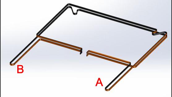
1. Take out the new synchronous belt, refer to CoreXY belt tying method for belt installation, Please noticed that the belt winding can’t be wrong. The length of the belt installation needs to be consistent, and use screws to fix the belt clip to complete the belt installation.
B、Calibrate X-axis parallelism again
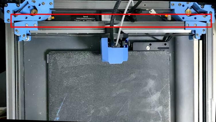
1. After the belt installation is completed, it needs to be calibrated again. Please push both ends of the X axis to push the X axis to the back end of the gantry frame at the same time. The X axis should be close to the AB axis motor seat backward, and there should be no gap between the X/Y joint and the A/B axis motor seat.
 |
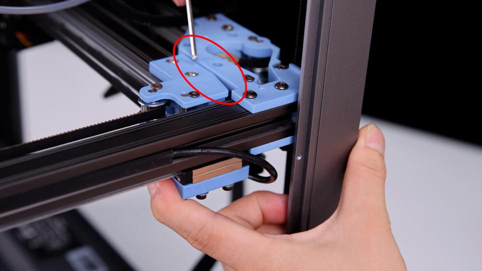 |
2.If there is a large gap, it is possible that the tension of the left and right sides of the belt is inconsistent, so the side of the larger tension will appear more obvious gap. In this case, the screw of the tensioner can be further tightened so that the belt is completely relaxed.
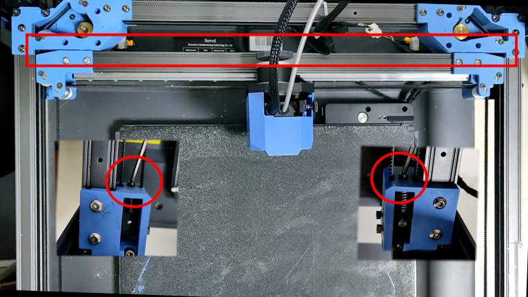
3.After ensuring that the X axis and the AB axis drive close, at the same time loosen the left and right sides of the tensioner screw three rings, so that the belt has a slight tension, and ensure that the X axis is still close to the AB axis drive.
¶ Use “Carbon drive” to debug the belt
Preparation for debugging.
Before the start of debugging, download “Carbon Drive” from the App Store. By testing the frequency of belt vibration, the software achieves the effect of adjusting the belt tension(debugging 3D printer using the “motorcycle” option), SV08 adjusts the frequency of the belt by changing the tensioner.
(Before debugging, please note: keep the environment quiet, the phone can not touch the synchronous belt or frame, remove the protective case of the phone, take more practice. At the same situation, until each recording can get a smaller range of fluctuations in the value, take the average value of the smaller deviation.)
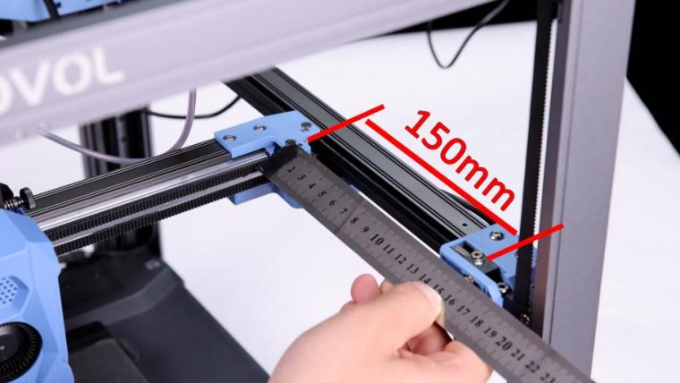
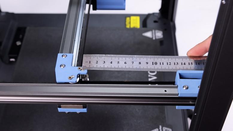
1. After installing the belt, please move the X axis forward at the same time. You can use a ruler to measure the distance between the idler center of X/Y and the A/B idler until the X/Y idler center is 150mm from the front idler center. Measure the other side at the same time, the distance must be the same. If the two sides are different, please repeat the steps to calibrate the parallelism of the X axis.

|
 |
 |
2. Installation: Install the calibration of synchronous belt software in the cell phone, “Spectroid”, Gates “Carbon drive”, It is recommend that you can use Gates software, because its usage is relatively more simple(can be downloaded in the Google App store, Apple users can download in the App Store.)
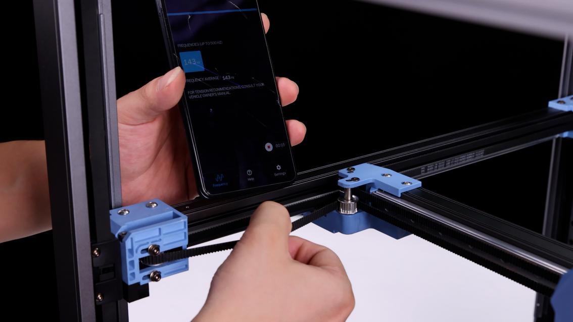
3、Open the APP, select the “Motorcycle Mode”, align the handset's earpiece with the synchronous belt (B idler pulley), use the appropriate force to vertically toggle the 150mm section of the synchronous belt, the software will automatically record the frequency of the synchronous belt. The A/B axis timing belts are optimal at 110 Hz. 110 Hz in this case is approximately equal to 1.8 kg of timing belt tension, which is at the lower end of the range. The software will record the frequency 3 times and automatically calculate the average value (if there is a larger or smaller value, it may be from the noise in the environment, please delete this type of value), dial the belt several times and record the average value of the first debugging.
 |
 |
 |
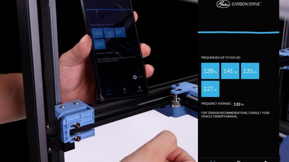 |
4. Vertically toggle the right side of the synchronous belt (A idler pulley), adjust the frequency of the synchronous belt about 110HZ, the deviation range should not exceed 10HZ (105Hz-115Hz), the synchronous belt tension of the A/B axis will affect each other. Tighten one and the other will change, so when adjusting the tensioner back and forth, loosen or tighten both sides together until they are roughly equal. (One revolution changes about 30Hz) The average frequency of the first toggle test was 132Hz.

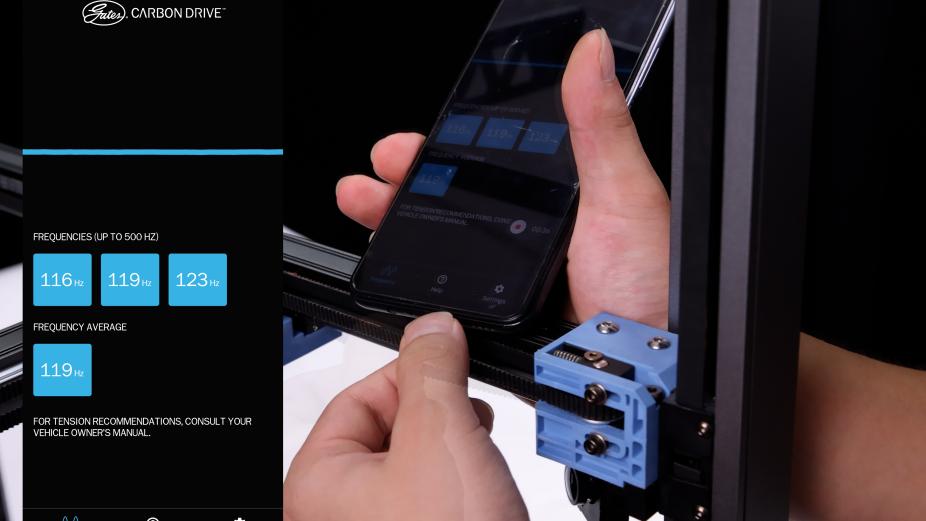
The average frequency is greater than 110Hz,
indicating that the belt is in a taut state,
you can properly tighten the tensioner screws to relax the belt and reduce the average frequency of the belt.
 |
 |
4. Repeat to verify the debugging results, push the X-axis backward for a few centimeters, and then move back to the original position (150mm) by measuring with a ruler, and then toggle the synchronous belt again, so that the synchronous belt's frequency is within the frequency range of step 3 and step 4, you can complete the adjustment of the AB-axis belt; after adjusting the finished belt, please move the X-axis to be tightly attached to the AB-axis driver to ensure that the X-axis left and right are tightly attached to the AB-axis driver, and the X-axis can be adjusted to be tightly attached to the AB-axis driver. As shown in the figure:
