¶ Installing OrcaSlicer
To avoid installation issues or software crashes during use, please refer to the following hardware requirements before installing the software:
¶ OrcaSlicer Minimum System Requirements
|
Component |
Requirement |
| Operating System |
Windows 7 / macOS 10.13 / Ubuntu 20.04 or newer (64-bit systems only) |
| Processor |
Intel Core i3 or equivalent |
| Memory (RAM) |
Minimum 4 GB (8 GB or higher recommended) |
| Storage Space |
At least 500 MB of available space |
| Graphics Support |
OpenGL 3.3 or higher (Windows/Linux) / Metal (macOS) |
Note: OrcaSlicer's minimum requirements are relatively low, particularly in terms of operating system compatibility and storage space.
¶ OrcaSlicer Installation Steps (Windows)
¶ Step 1:Download and Install
1.Locate the OrcaSlicer installation package on the provided USB drive, or download it from the Wiki page using the link below, then run the installer.
Wiki Link:
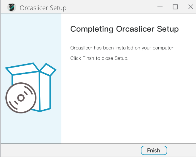
2.Install OrcaSlicer by following the on-screen prompts to add printer models and materials.
If you need to preserve your previous OrcaSlicer configuration files, skip to Step 3 below.
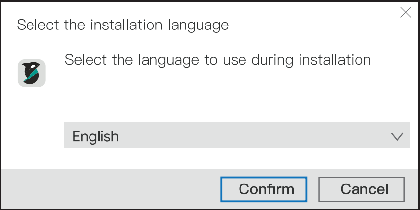
(1)OrcaSlicer currently supports 15 languages. Select your preferred language for installation.
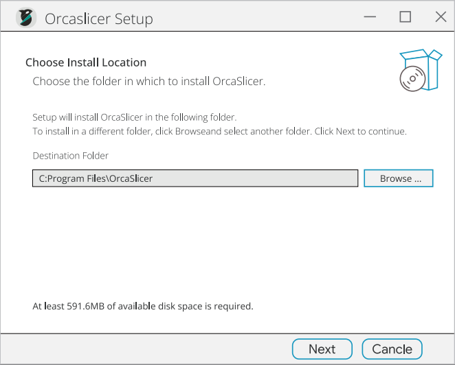
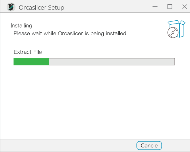
(2) Follow the installation prompts. The installation path can be modified—it is recommended to install on a drive other than the system (C:) drive.
 |
 |
 |
| Note: If the software fails to launch after installation (e.g., clicking the icon does nothing), please install VC_redist.x64.exe. This is a critical runtime component required by many professional applications, providing the C++ standard library and runtime environment. |
¶ Step 2:Select Printer Model and Filament
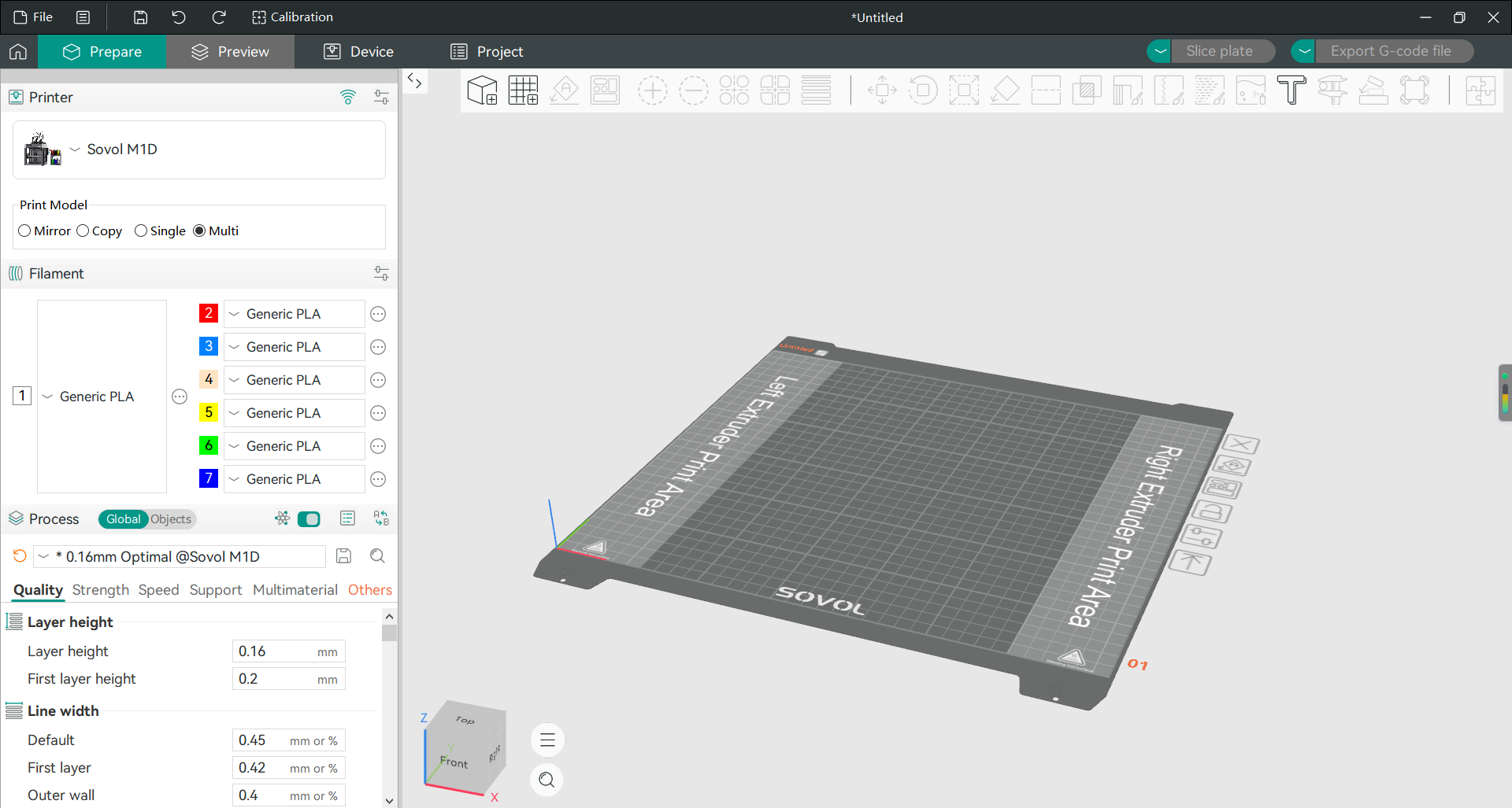
(3) After installation is complete, launch OrcaSlicer and follow the software prompts to configure settings.
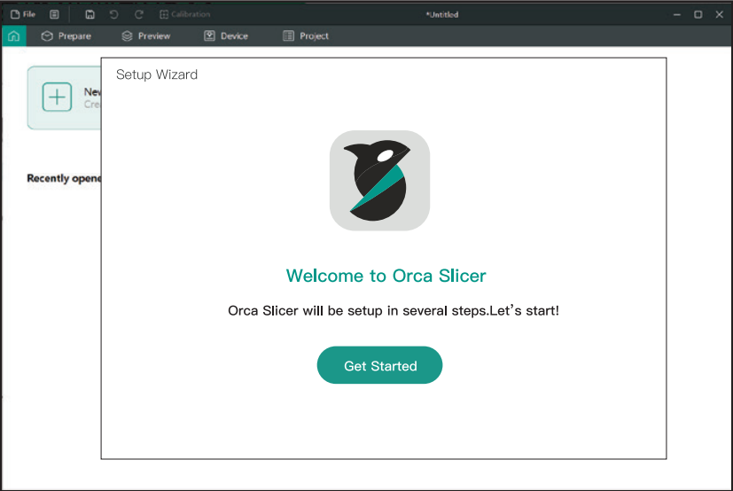
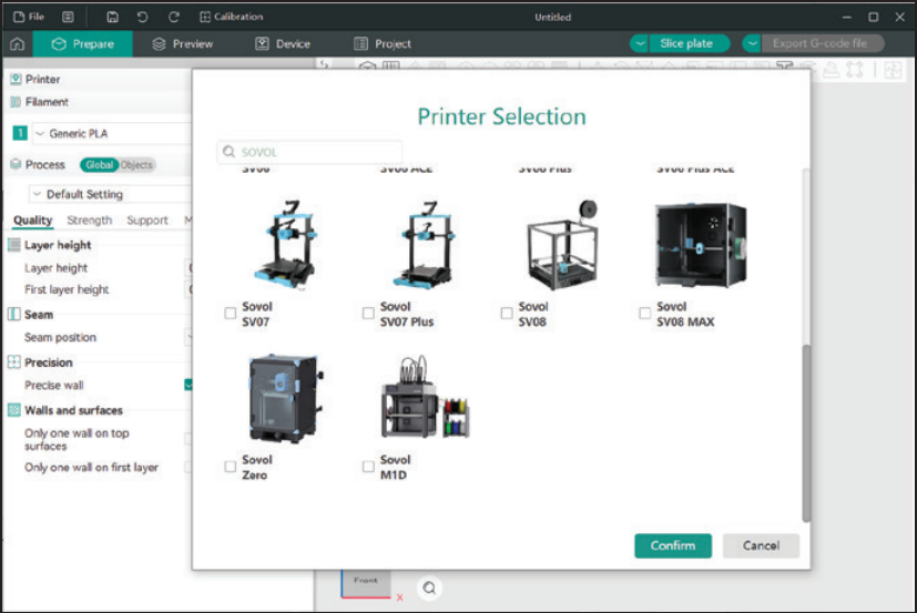
(4) In the search bar, type "SOVOL" and add the M1D printer model.
(5) Select the filament brand and type to complete the setup.
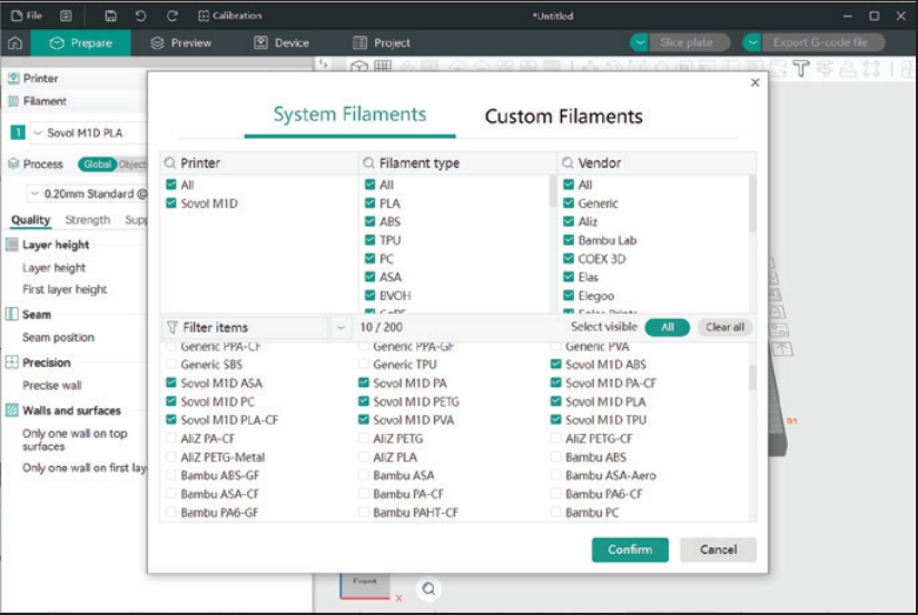
(6) Installation is now complete.
¶ Step 3:Import Models and Slice
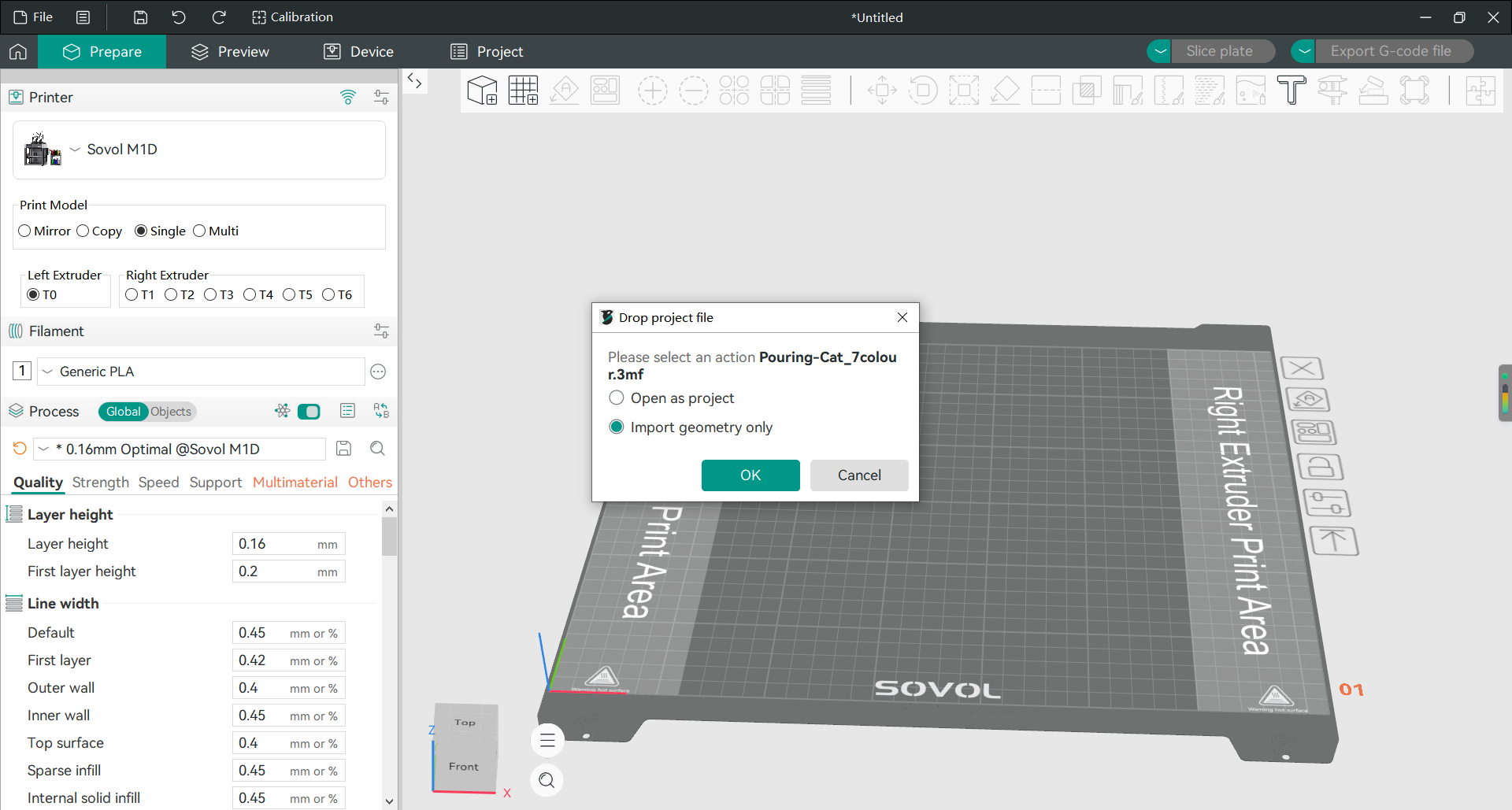
1) Import 3D models into the software. OrcaSlicer supports model files in formats such as STL, STEP, and 3MF. When importing 3MF files, you can choose in "Preferences" whether to "Load Geometry Only" or "Load Geometry and Settings". If the 3MF file contains process parameters, OrcaSlicer will automatically attempt to apply them.
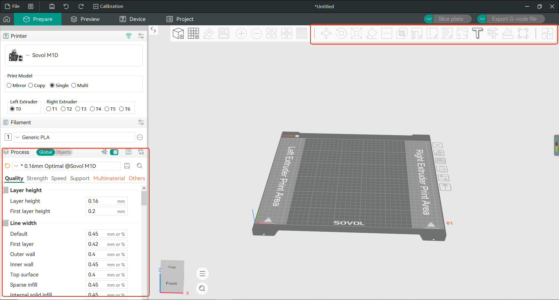
2) Select the model. The toolbar provides common operations including Scale, Mirror, and Cut. The parameter settings panel on the left allows you to modify print parameters such as Strength, Print Speed, and Support settings.
3) After configuring the parameters, you can select the slicing method and export G code files from the upper right corner of the interface:
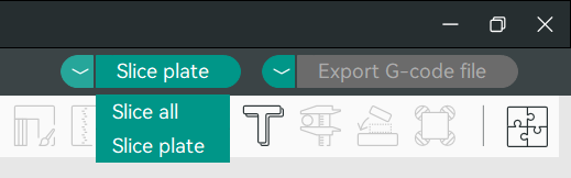
Slice Single Plate : only the currently selected plate
Slice All Plates : Slice all plates in sequence
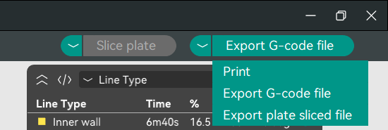
Print: Transfers the G-code file to the connected printer and begins printing.
Export G-code file: Generates a standard G-code file for USB transfer. Select the print file on the screen.
Export plate sliced file: Exports the sliced project file, saved as a .3mf file, containing model geometry data and all slice parameters (layer height, speed, supports, etc.).
¶ Step 4:Start Your First Print
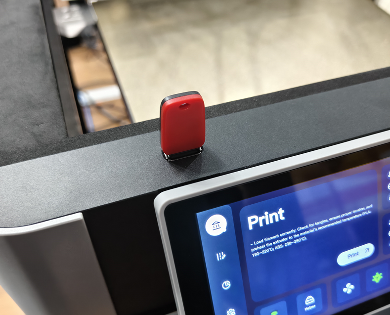
3) USB Print: Insert the USB drive into the machine, tap "Leave for" on the screen, and select the file to print.
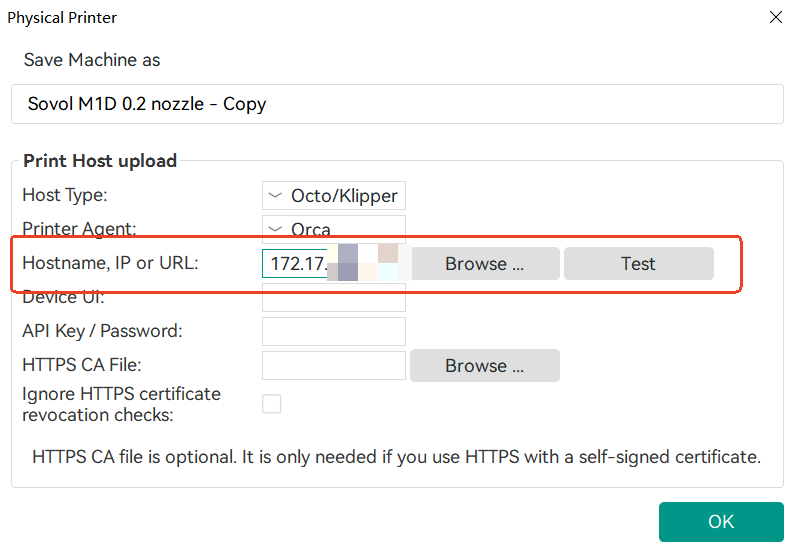
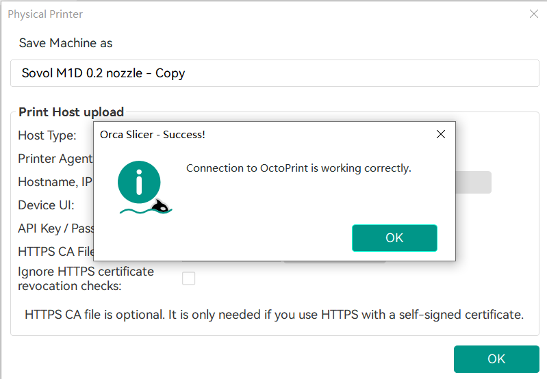
4) Network Print: Connect via IP address and send the print task.
 |
 |
5) First Print Complete: Successfully complete the test print.
¶ Print Mode Switching
The M1D utilizes the INDX Multi-Head System, featuring dual toolheads with the right print head supporting quick-change hotends, enabling seamless switching between multiple materials and colors. Whether for single-nozzle printing, mirror printing, copy printing, or multi-color creation, the M1D significantly improves printing efficiency, allowing a single device to serve multiple purposes.
Below is an introduction to the four print modes and their usage:
¶ Single-Nozzle Printing
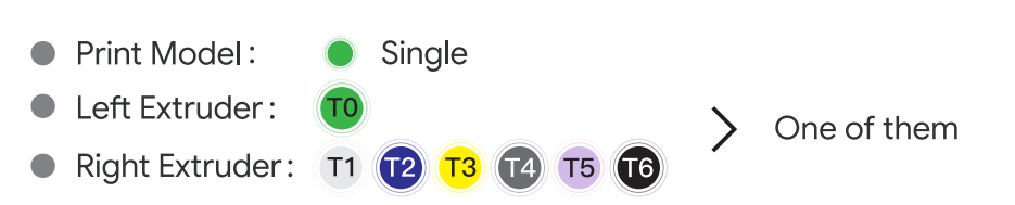
Uses only a single print head for conventional printing, with the other print head remaining idle. Suitable for everyday model production.
In this mode, only one toolhead participates in the printing process.The available printing area is 300 × 300 mm
(the grayed-out area indicates the toolhead parking zone where models cannot be placed).
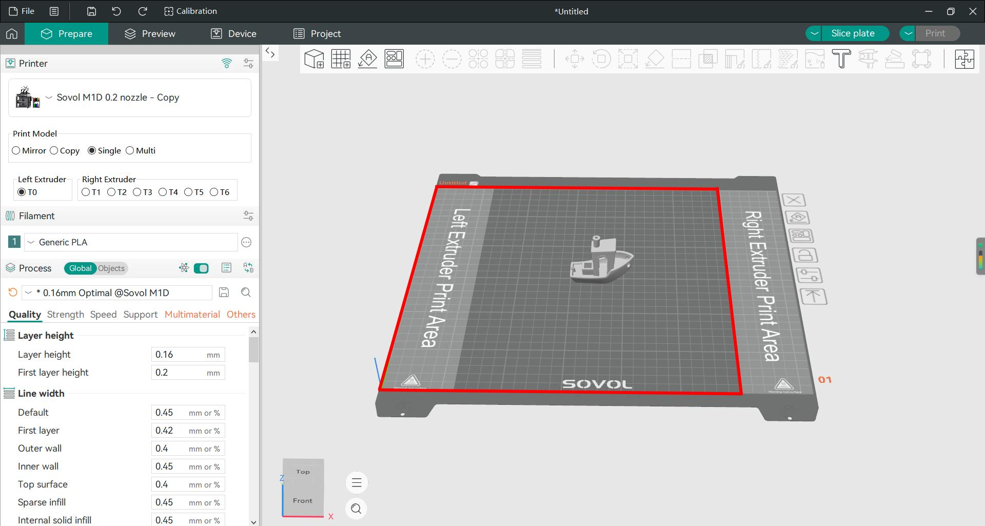 Left Extruder Printing area(300*300) |
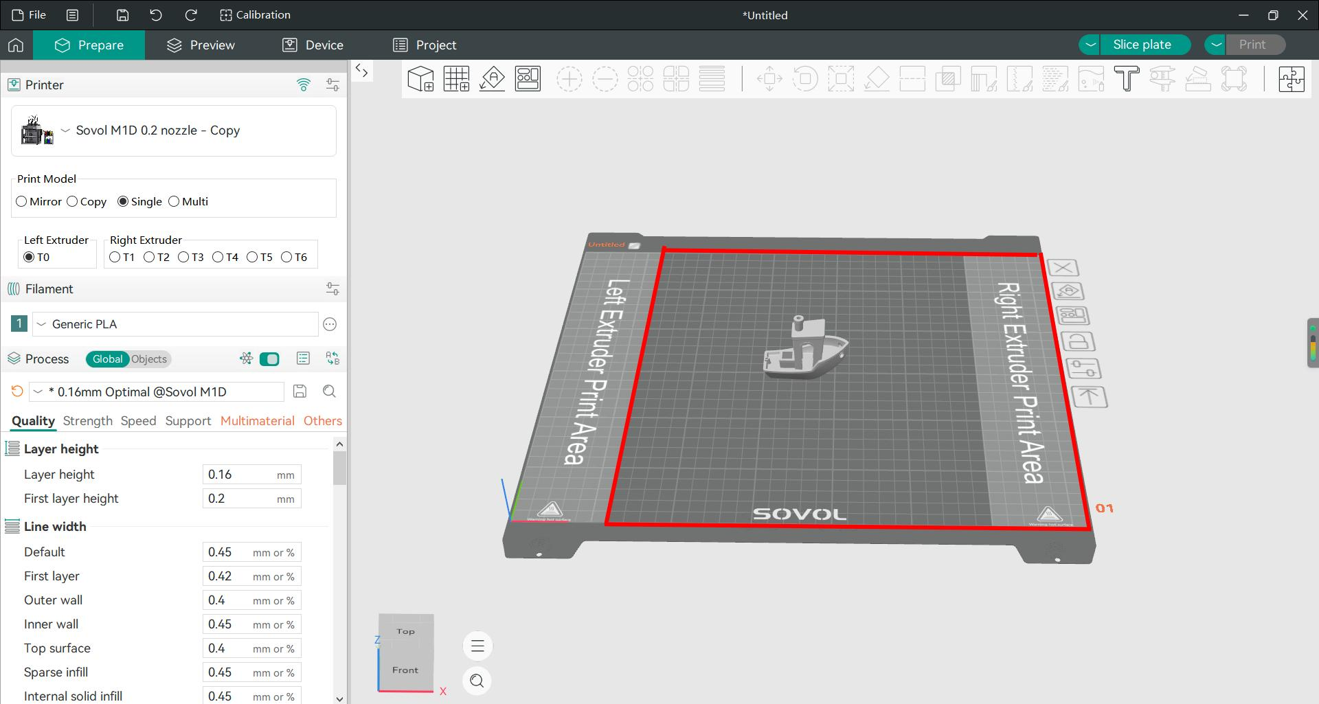 Right Extruder Printing area(300*300) |
Advantages: Simple operation, no complex setup required, ideal for rapid prototype validation.
¶ Mirror Mode Printing

Both toolheads print left-right symmetrical models simultaneously. The slicing software automatically generates mirrored models, producing a pair of perfectly symmetrical parts in a single print—no post-processing mirroring required. (The grayed-out area indicates where models cannot be placed. Simply slice the selected model and switch to Mirror Mode—the toolheads will automatically execute mirror printing.)
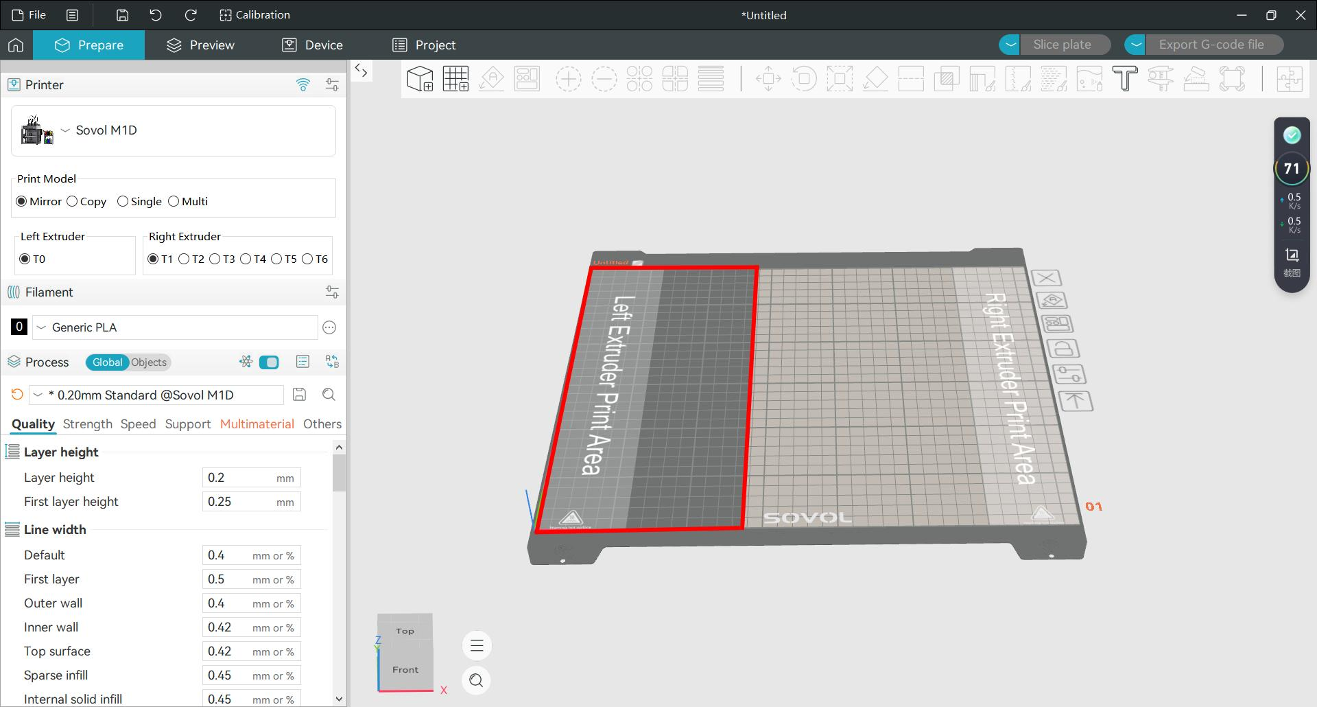

Applications: Ideal for printing paired components such as left/right shoe molds, left/right shells, left/right handles, etc., significantly improving printing efficiency.
¶ Copy Mode Printing

In this mode, the slicing software virtually divides the build platform into two independent zones (left and right). The left nozzle prints models in the left zone while the right nozzle simultaneously prints identical mo dels in the right zone. Both nozzles work concurrently, dramatically increasing printing throughput. (The grayed-out area indicates where models cannot be placed. Simply slice the selected model and switch to Copy Mode—the toolheads will automatically execute copy printing.)
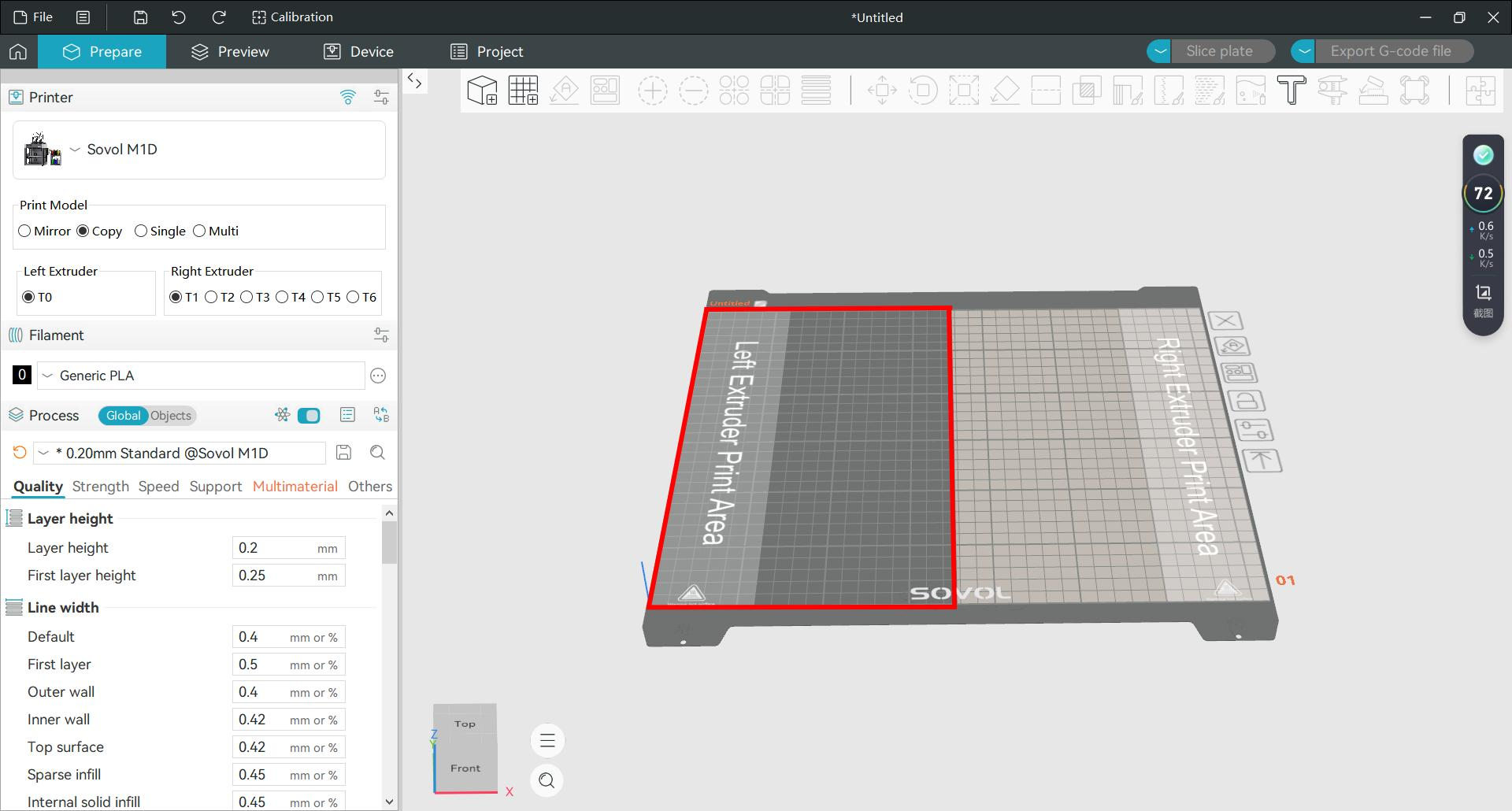

Applications: Doubles output within the same timeframe—ideal for scenarios requiring rapid production of multiple identical models.
¶ Multi-Nozzle Printing
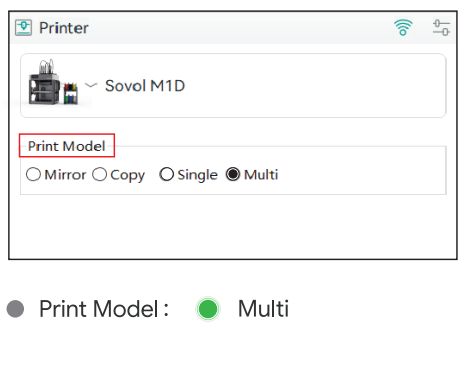
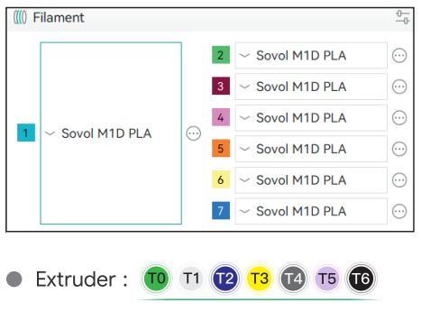
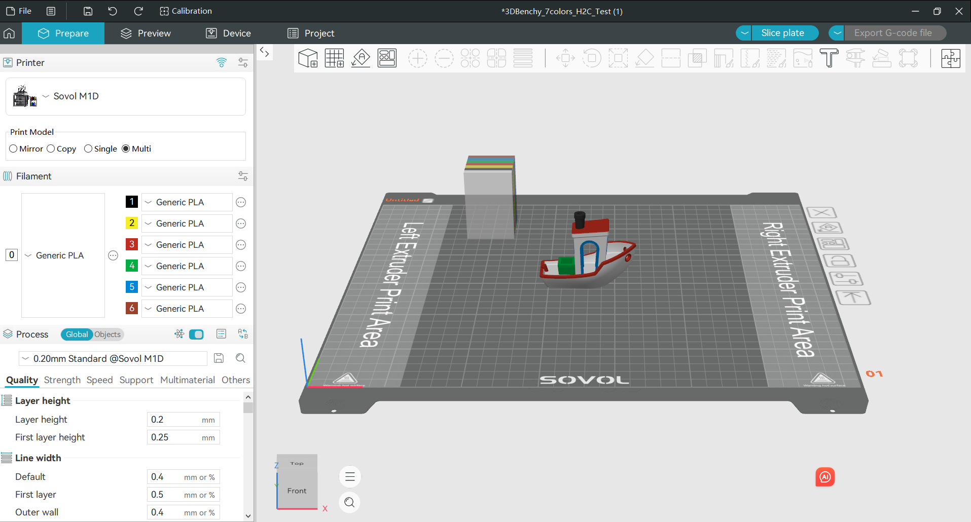
Different parts or layers of the same model are printed with different colors or materials by the two toolheads.The left toolhead prints one material while the right toolhead prints another, alternating to complete the entire model.
(The grayed-out area indicates where models cannot be placed.)
 |
 |
Important Notes
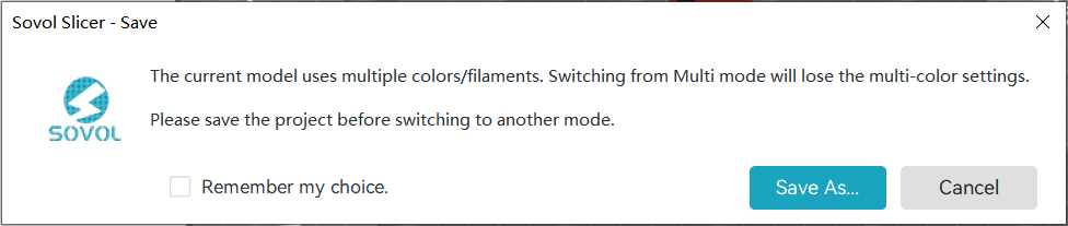
1.When switching from Multi mode to Single, Copy or Mirror mode, all slice colours you have set will be cleared; please save your settings before switching.
2.Before importing or exporting 3MF multi-colour slice files, please ensure that Orcaslicer is set to Multi mode.