How to troubleshoot "Lost communication with MCU 'extra_mcu' "
The printer reports in the Mainsail interface that it has lost communication with the mcu:
Klipper reports: SHUT DOWN
Lost communication with MCU 'extra_mcu'Once the underlying issue is corrected, use the "FIRMWARE_RESTART" command to reset the firmware, reload the config, and restart the host software.
Printer is shutdown
Tools: Multimeter

Pin diagram of the adapter board:

¶ 1.Overall hardware test (mainboard, adapter board, signal cable)
1. Turn off the power, unplug the AC power cord, use the Fluke multimeter, adjust to the resistance range, and connect the negative probe to GND as shown in Figure 1.
 |
 |
2. According to Figure 1, connect the negative probe to GND and the positive probe to UN. The resistance is about 0.58M, which is normal. The smaller it is, the more serious the damage. If it is infinite, the metal end of the wire is loose.

3.According to Figure 1, connect the negative probe to GND and the positive probe to UP. The resistance is about 2K-2.8K, which is normal. The smaller it is, the more serious the damage.
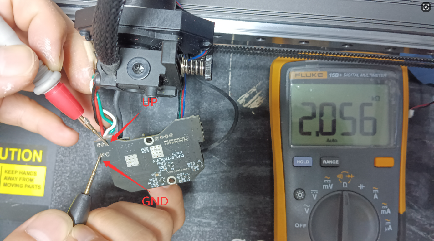
4. According to Figure 1, connect the negative probe to GND and the positive probe to 24V. The resistance is about 1M-30M, which is normal. If it is infinite, there are two situations.
a. If item 4 is normal in the adapter board test of (II. Adapter board test), the metal end spring clip of the line is loose;
b. If item 4 is abnormal in the adapter board test of (II. Adapter board test), the nozzle board is broken.
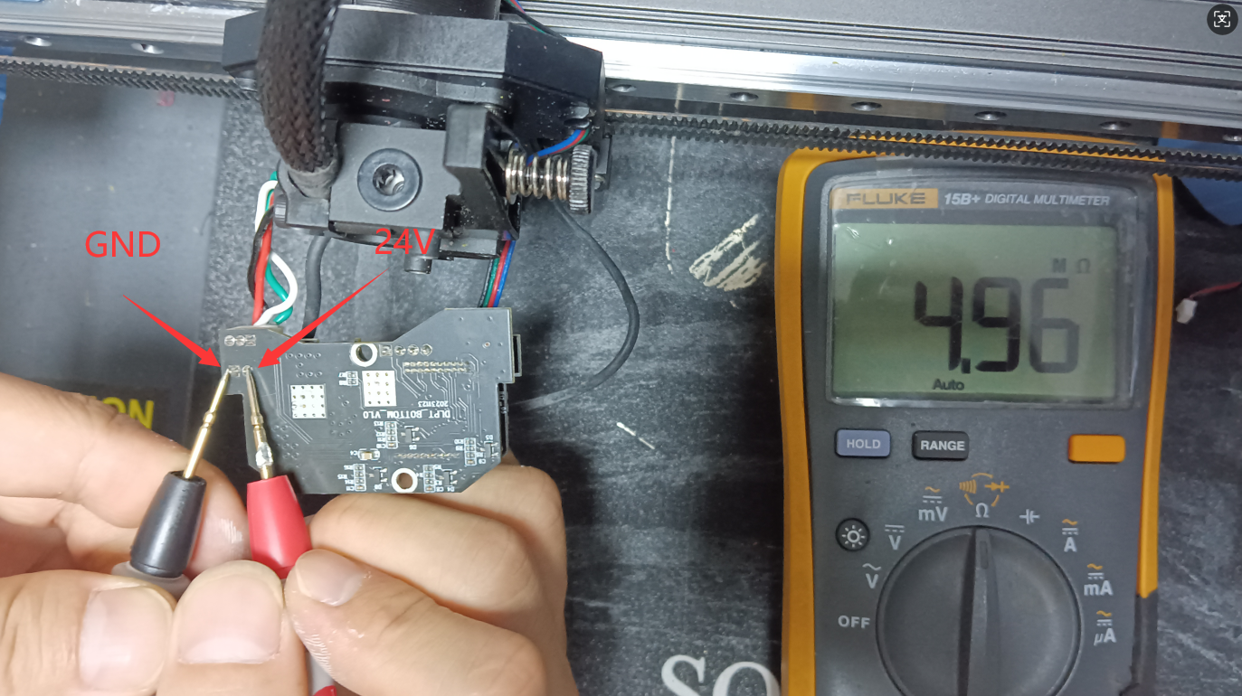
5.If it is not normal, please continue to test the next step
¶ 2.Adapter board test
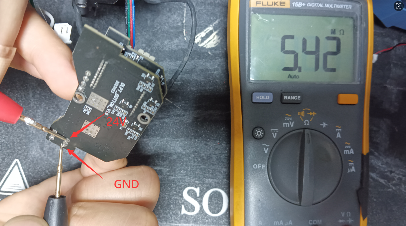
1. Unplug the two cables(signal cables) in the box in Figure 2, use a Fluke multimeter, adjust it to the resistance range, and connect the negative probe to GND according to Figure 1.

|
 |
2.According to Figure 1, connect the negative probe to GND and the positive probe to UN. The resistance is infinite, which is normal. The smaller it is, the more serious the damage.
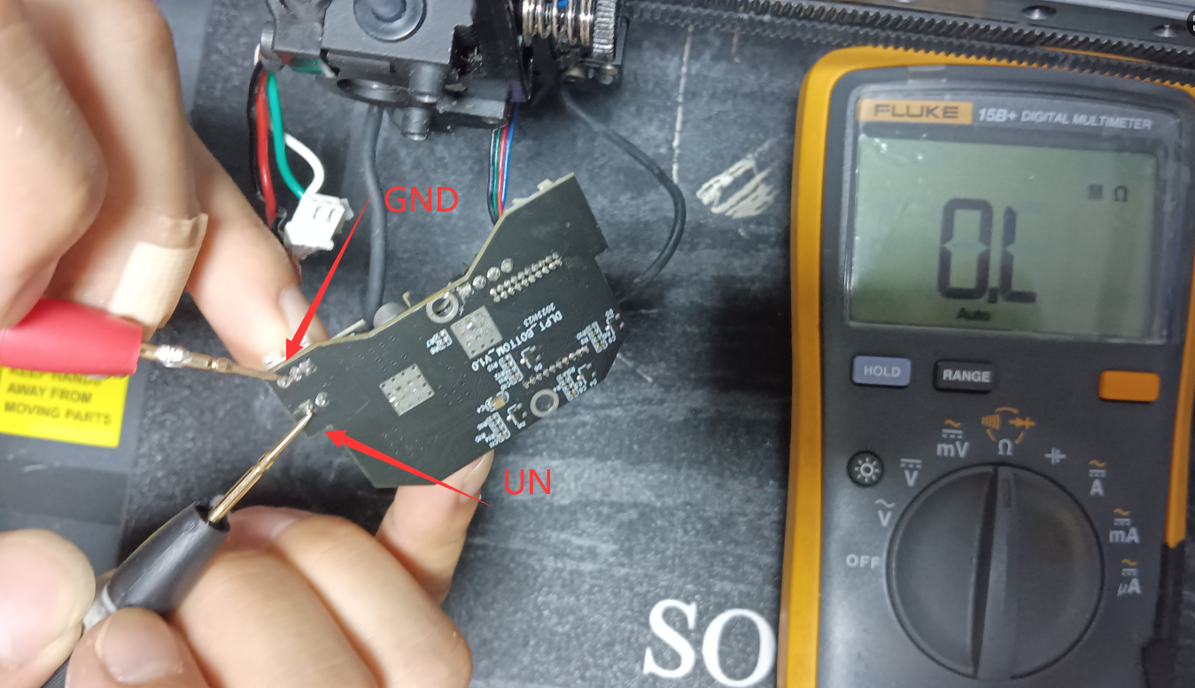
3. According to Figure 1, connect the negative probe to GND and the positive probe to UP. The resistance is about 2K-2.8K, which is normal. The smaller it is, the more serious the damage.
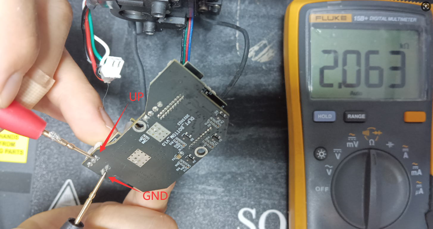
4. According to Figure 1, connect the negative probe to GND and the positive probe to 24V. The resistance is about 1M-30M, which is normal. The larger the resistance, the more serious the damage. Complete damage is infinite.
¶ 3.Mainboard & Signal Cable Test
1. Unplug the signal cables in the figure, adjust the Fluke multimeter to the resistance range, and connect the negative probe to GND (signal line) as shown in Figure 3.


2. According to Figure 3, connect the negative probe to GND (signal line) and the positive probe to UN (line). The resistance is about 0.6M, which is normal. The smaller the resistance, the more serious the damage.
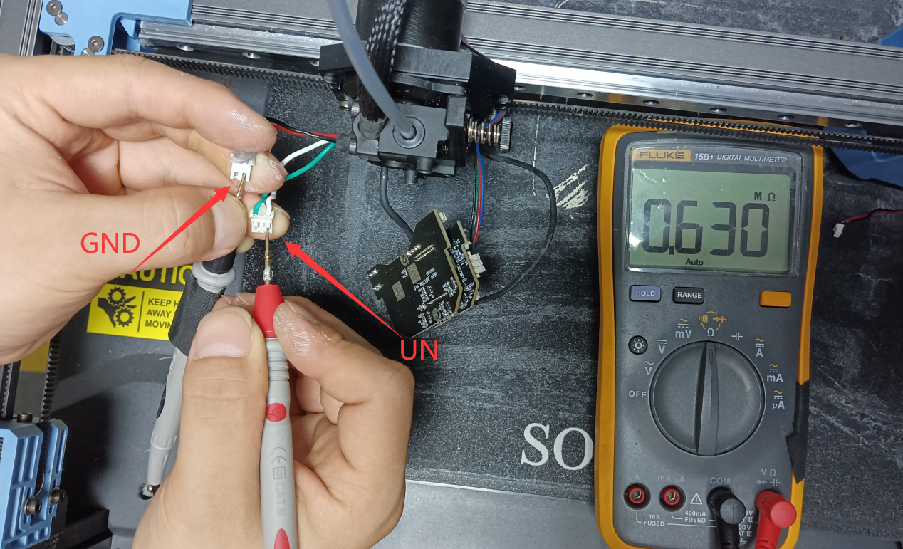
3. According to Figure 3, connect the negative probe to GND (signal line) and the positive probe to UP (line). The resistance is about 0.6M, which is normal. The smaller it is, the more serious the damage. If it is infinite, the metal end of the mainboard end line is loose.

¶ 4.Judgment results:
1. If the overall test is normal, the mainboard, adapter board, and signal line are all normal.
a. If the communication is interrupted during printing, it may be that the metal terminal spring clip of the line is loose during printing. Use tweezers to restore the metal terminal spring clip.
b. If the communication is interrupted when the machine is turned on, it means that the configuration file has been changed or there is a bug in the system.
2. If the overall test is abnormal, it may be that the mainboard, adapter board, or signal line is faulty. Replace the corresponding accessories.